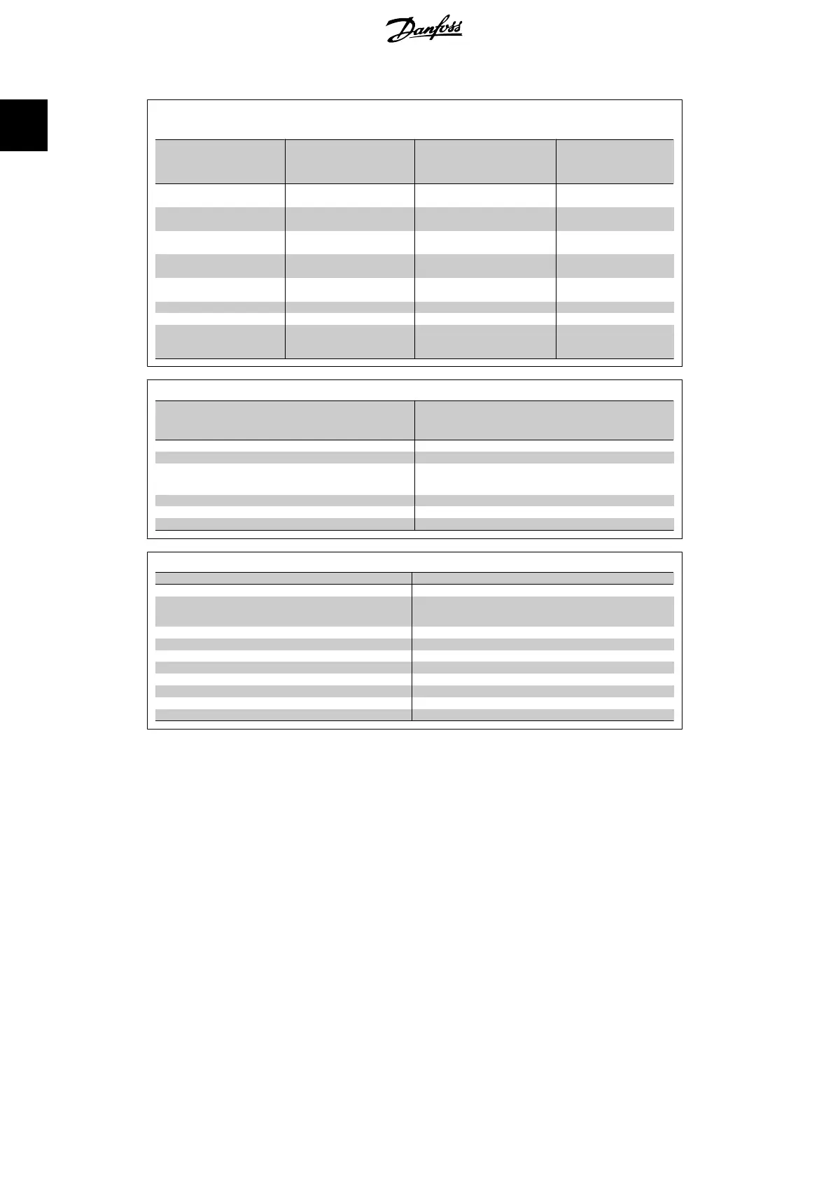
Q3-1 General Settings
Q3-10 Clock Settings Q3-11 Display Settings Q3-12 Analog Output Q3-13 Relays
0-70 Set Date and Time 0-20 Display Line 1.1 Small 6-50 Terminal 42 Output
Relay 1 ⇒ 5-40 Function
Relay
0-71 Date Format 0-21 Display Line 1.2 Small 6-51 Terminal 42 Output Min
Scale
Relay 2 ⇒ 5-40 Function
Relay
0-72 Time Format 0-22 Display Line 1.3 Small 6-52 Terminal 42 Output Max
Scale
Option relay 7 ⇒ 5-40
Function Relay
0-74 DST/Summertime 0-23 Display Line 2 Large
Option relay 8 ⇒ 5-40
Function Relay
0-76 DST/Summertime Start 0-24 Display Line 3 Large
Option relay 9 ⇒ 5-40
Function Relay
0-77 DST/Summertime End 0-37 Display Text 1
0-38 Display Text 2
0-39 Display Text 3
Q3-2 Open Loop Settings
Q3-20 Digital Reference Q3-21 Analog Reference
3-02 Minimum Reference 3-02 Minimum Reference
3-03 Maximum Reference 3-03 Maximum Reference
3-10 Preset Reference 6-10 Terminal 53 Low Voltage
5-13 Terminal 29 Digital Input 6-11 Terminal 53 High Voltage
5-14 Terminal 32 Digital Input 6-14 Terminal 53 Low Ref/Feedb. Value
5-15 Terminal 33 Digital Input 6-15 Terminal 53 High Ref/Feedb. Value
Q3-3 Closed Loop Settings
Q3-30 Feedback Settings Q3-31 PID Settings
1-00 Configuration Mode 20-81 PID Normal/Inverse Control
20-12 Reference/Feedb.Unit 20-82 PID Start Speed [RPM]
3-02 Minimum Reference 20-21 Setpoint 1
3-03 Maximum Reference 20-93 PID Proportional Gain
6-20 Terminal 54 Low Voltage 20-94 PID Integral Time
6-21 Terminal 54 High Voltage
6-24 Terminal 54 Low Ref/Feedb Value
6-25 Terminal 54 High Ref/Feedb Value
6-00 Live Zero Timeout Time
6-01 Live Zero Timeout Function
1. How to Programme VLT
®
AQUA Drive Programming Guide
18
MG.20.O2.02 - VLT
®
is a registered Danfoss trademark
1
 Loading...


