23-65 Minimum Bin Value
Range: Function:
[0 - 100%] Array with 10 elements ([0]-[9] below parameter number in
display). Press OK and step between elements by means of ▲
and ▼ buttons on the LCP.
Set the minimum limit for each interval in par. 23-61,
Continu-
ous Bin Data
, and par. 23-62,
Timed Bin Data
. Example: if
selecting
counter
[1] and changing setting from 10% to 12%,
counter
[0] will be based on the interval 0 - <12% and
coun-
ter
[1] on interval 12% - <20%.
23-66 Reset Continuous Bin Data
Option: Function:
[0]
*
Do not reset
[1] Do reset Select
Do reset
[1] to reset all values in par. 23-61,
Continuous
Bin Data
.
After pressing OK the setting of the parameter value will auto-
matically change to
Do not reset
[0].
23-67 Reset Timed Bin Data
Option: Function:
[0]
*
Do not reset
[1] Do reset Select
Do reset
[1] to reset all counters in par. 23-62,
Timed Bin
Data
.
After pressing OK the setting of the parameter value will auto-
matically change to
Do not reset
[0].
2.20.5. 23-8* Payback counter
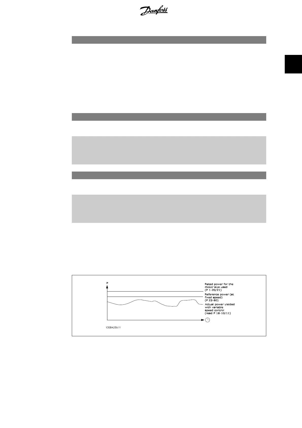
The VLT AQUA Drive includes a feature which can give a rough calculation on payback in cases
where the frequency converter has been installed in an existing plant to ensure energy saving by
changing from fixed to variable speed control. Reference for the savings is a set value to represent
the average power yielded before the upgrade with variable speed control.
The difference between the Reference Power at fixed speed and the Actual Power yielded with
speed control represent the actual saving.
As value for the fixed speed case, the rated motor size (kW) is multiplied with a factor (set in %)
representing the power yielded at fixed speed. The difference between this reference power and
VLT
®
AQUA Drive Programming Guide 2. Parameter Description
MG.20.O2.02 - VLT
®
is a registered Danfoss trademark
225
2
 Loading...


