[201] Pump1 Running One or more of the pumps controlled by the Cascade Controller
are running. The function will also depend on the setting of in
Fixed Lead Pump
, par. 25-06. If set to
No
[0] Pump 1 refers to
the pump controlled by relay RELAY1 etc. If set to
Yes
[1] Pump
1 refers to the pump controlled by the frequency converter only
(without any of the build in relays involved) and Pump 2 to the
pump controlled by the relay RELAY1. See below table:
[202] Pump2 Running See [201]
[203] Pump3 Running See [201]
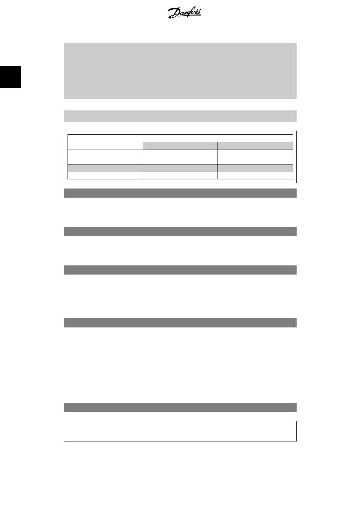
Setting in Par. 5-3*
Setting in Par. 25-06
[0] No [1] Yes
[200] Pump 1 Running Controlled by RELAY1 Frequency Converter control-
led
[201] Pump 2 Running Controlled by RELAY2 Controlled by RELAY1
[203] Pump 3 Running Controlled by RELAY3 Controlled by RELAY2
5-30 Terminal 27 Digital Output
Option: Function:
[0]
*
No Operation Same options and functions as par. 5-3*, Digital Outputs.
5-31 Terminal 29 Digital Output
Option: Function:
[0]
*
No Operation Same options and functions as par. 5-3*, Digital Outputs.
5-32 Terminal X30/6 Digital Output (MCB 101)
Option: Function:
[0]
*
No operation This parameter is active when option module MCB 101 is moun-
ted in the frequency converter.
5-33 Terminal X30/7 Digital Output (MCB 101)
Option: Function:
[0]
*
No operation This parameter is active when option module MCB 101 is moun-
ted in the frequency converter.
2.7.5. 5-4* Relays
Parameters for configuring the timing and the output functions for the relays.
5-40 Function Relay
Array [8] (Relay 1 [0], Relay 2 [1], Relay 7 [6], Relay 8 [7], Relay 9
[8])
Select options to define the function of the relays.
2. Parameter Description VLT
®
AQUA Drive Programming Guide
88
MG.20.O2.02 - VLT
®
is a registered Danfoss trademark
2
 Loading...


