[169] Drive in auto mode Output is high when the frequency converter is in Hand on mode
(as indicated by the LED light above [Auto on].
[180] Clock Fault The clock function has been reset to default (2000-01-01) be-
cause of a power failure.
[181] Preventive Mainte-
nance
One or more of the Preventive Maintenance Events programmed
in par. 23-10, Preventive Maintenance Item, has passed the
time for the specified action in par. 23-11, Maintenance Action.
[190] No-Flow A No-Flow situation or Minimum Speed situation has been de-
tected if enabled in
Minimum Speed Detection
. par. 22-21 and/
or
No-Flow Detection
, par. 22-22.
[191] Dry Pump A Dry Pump condition has been detected. This function must be
enabled in par. 22-26, Dry Pump Function.
[192] End of Curve Active when an End of Curve condition is present.
[193] Sleep Mode The frequency converter/system has turned into sleep mode.
See
Sleep mode
, par. 22-4*.
[194] Broken Belt A Broken Belt condition has been detected. This function must
be enabled in par. 22-60, Broken Belt Detection.
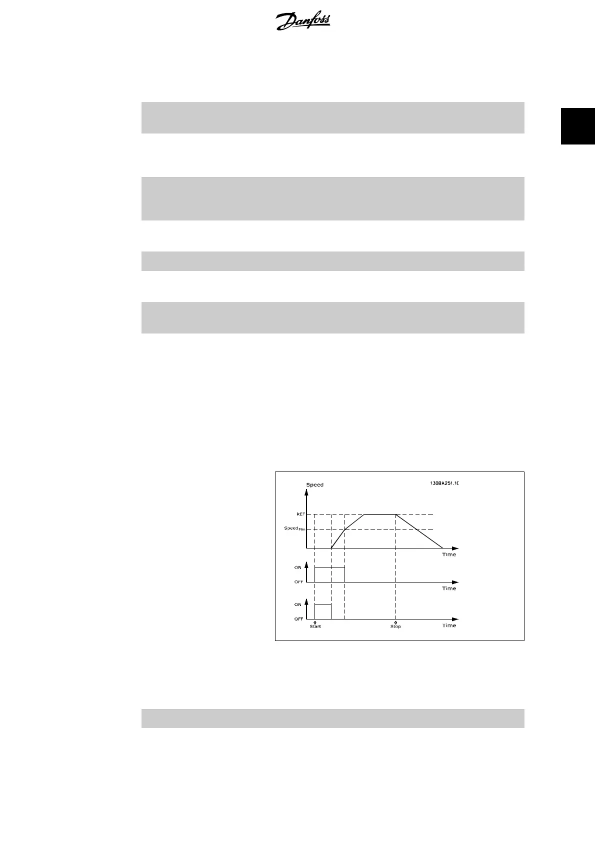
[195] Bypass Valve Control The bypass valve control (Digital / Relay output in the frequency
converter) is used for compressor systems to unload the com-
pressor during start-up by using a bypass valve. After the start
command is given the bypass valve will be open until the fre-
quency converter reaches
Motor speed low limit
, par. 4 -11) .
After the limit has been reached the bypass valve will be closed,
allowing the compressor to operate normally. This procedure
will not be activated again before a new start is initiated and the
frequency converter speed is zero during the receiving of start
signal.
Start Delay
, par. 1-71 can be used in order to delay the
motor start. The Bypass valve control principle:
The below setting options are all related to the Cascade Controller.
Wiring diagrams and settings for parameter, see group 25-** for more details.
[196] Pipe Filling Active when the Pipe Fill function is operating. See par. 29-0*.
[200] Full Capacity All pumps running and at full speed
VLT
®
AQUA Drive Programming Guide 2. Parameter Description
MG.20.O2.02 - VLT
®
is a registered Danfoss trademark
87
2
 Loading...


