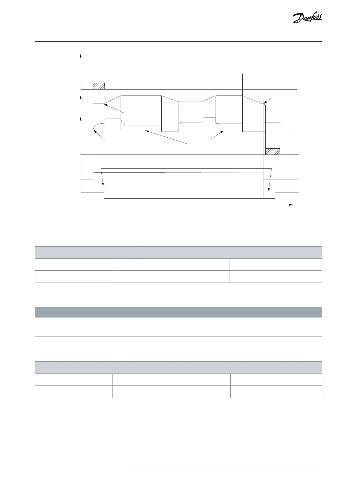
Start delay time
on
off
Brake delay time
Time
Output current
Relay 01
Pre-magnetizing
current or
DC hold current
Reaction time EMK brake
Par 2-20
Release brake current
Par 1-76 Start current/
Par 2-00 DC hold current
Activate brake
speed
Mechanical brake
locked
Mechanical brake
free
Illustration 45: Mechanical Braking
Parameter 2-20 Release Brake Current
Table 168: Parameter 2-20 Release Brake Current
2-20 Release Brake Current
Default value: Size related
Parameter type: Range, 10 - par. 16-37 A
Change during operation: True
Set the motor current for release of the mechanical braking when a start condition is present. The default value is the maximum
current the inverter can provide for the particular power size. The upper limit is specified in parameter 16-37 Inv. Max. Current.
N O T I C E
When mechanical brake control output is selected, but no mechanical braking is connected, the function does not work by de-
fault setting due to too low motor current.
Parameter 2-21 Activate Brake Speed [RPM]
Table 169: Parameter 2-21 Activate Brake Speed [RPM]
2-21 Activate Brake Speed [RPM]
Default value: Size related
Parameter type: Range, 0 - par. 4-53 RPM
Change during operation: True
Set the motor speed for activation of the mechanical braking when a stop condition is present.
AU275636650261en-000101 / 130R0334 | 119Danfoss A/S © 2022.12
Parameter Descriptions
VLT AutomationDrive FC 301/302
Programming Guide
 Loading...


