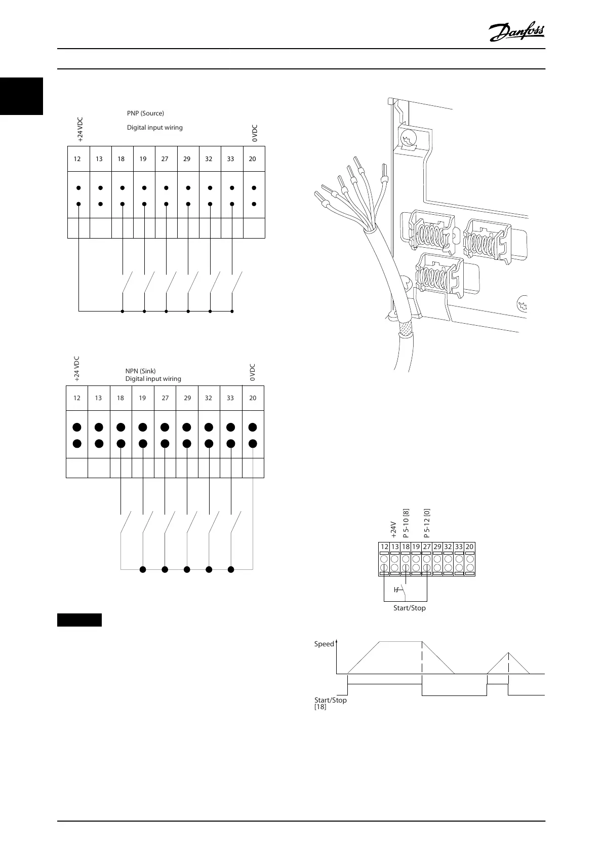
Input polarity of control terminals
Illustration 1.3 PNP (Source)
Illustration 1.4 NPN (Sink)
NOTICE
Control cables must be shielded/armored.
See the section Grounding of Shielded Control Cables in the
design guide for the correct termination of control cables.
Illustration 1.5 Grounding of Shielded/Armored Control Cables
1.3.1 Start/Stop
Terminal 18 = Parameter 5-10 Terminal 18 Digital Input [8]
Start.
Terminal 27 = Parameter 5-12 Terminal 27 Digital Input [0]
No operation (Default [2] Coast inverse).
Illustration 1.6 Start/Stop
Introduction VLT® AutomationDrive FC 361
8 Danfoss A/S © 03/2019 All rights reserved. MG06J202
11
 Loading...


