4.6 Parameters: 5-** Digital In/Out
4.6.1 5-0* Digital I/O Mode
Parameters for conguring the input and output using
NPN and PNP.
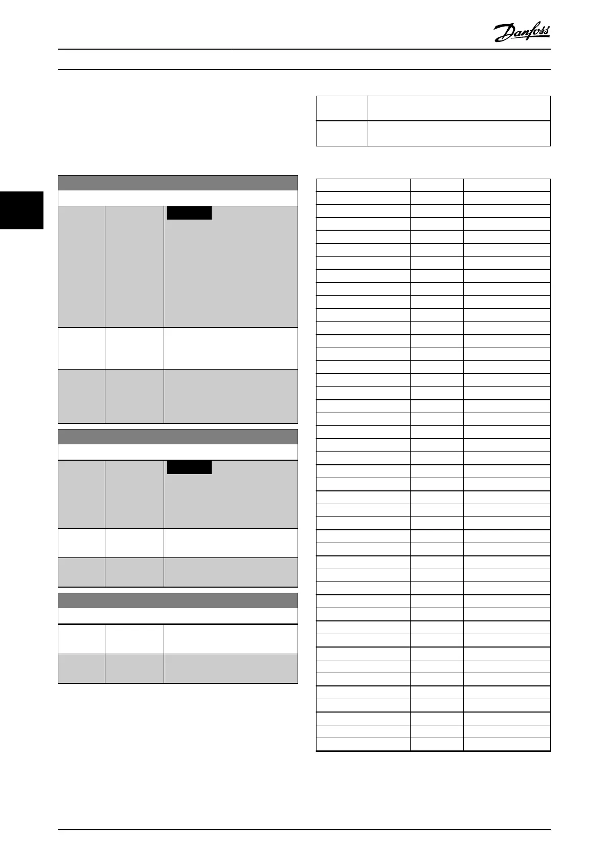
5-00 Digital I/O Mode
Option: Function:
NOTICE
Perform a power cycle to
activate the parameter once it
has been changed.
Digital inputs and programmed
digital outputs are pre-
programmable for operation either
in PNP or NPN systems.
[0] * PNP Action on positive directional pulses
(↕). PNP systems are pulled down
to GND.
[1] NPN Action on negative directional
pulses (↕). NPN systems are pulled
up to +24 V, internally in the
frequency converter.
5-01 Terminal 27 Mode
Option: Function:
NOTICE
This parameter cannot be
adjusted while the motor is
running.
[0] * Input Denes terminal 27 as a digital
input.
[1] Output Denes terminal 27 as a digital
output.
5-02 Terminal 29 Mode
Option: Function:
[0] * Input Denes terminal 29 as a digital
input.
[1] Output Denes terminal 29 as a digital
output.
The digital inputs are used for selecting various functions
in the frequency converter. Table 4.8 shows which functions
can be assigned to digital inputs.
Functions in group 1 have higher priority than functions in
group 2.
Group 1 Reset, coast stop, reset, and coast stop, quick stop,
DC brake, stop, and the [O] key.
Group 2 Start, latched start, reversing, start reversing, jog,
and freeze output.
Table 4.7 Function Groups
Digital input function Select Terminal
No operation [0] All, terminal 32, 33
Reset [1] All
Coast inverse [2] All, terminal 27
Coast and reset inverse [3] All
Quick stop inverse [4] All
DC brake inverse [5] All
Stop inverse [6] All
Start [8] All, terminal 18
Latched start [9] All
Reversing [10] All, terminal 19
Start reversing [11] All
Enable start forward [12] All
Enable start reverse [13] All
Jog [14] All, terminal 29
Preset reference on [15] All
Preset ref bit 0 [16] All
Preset ref bit 1 [17] All
Preset ref bit 2 [18] All
Freeze reference [19] All
Freeze output [20] All
Speed up [21] All
Speed down [22] All
Set-up select bit 0 [23] All
Set-up select bit 1 [24] All
Catch up [28] All
Slow down [29] All
Counter input [30] 29, 33
Pulse input time based [32] 29, 33
Ramp bit 0 [34] All
Ramp bit 1 [35] All
External interlock [51] –
DigiPot increase [55] All
DigiPot decrease [56] All
DigiPot clear [57] All
Counter A (up) [60] 29, 33
Counter A (down) [61] 29, 33
Reset Counter A [62] All
Counter B (up) [63] 29, 33
Counter B (down) [64] 29, 33
Reset counter B [65] All
PID error inv. [72] All
PID reset I-part [73] All
PID enable [74] All
Table 4.8 Digital Input Function
Parameter Descriptions VLT® AutomationDrive FC 361
66 Danfoss A/S © 03/2019 All rights reserved. MG06J202
44
 Loading...


