The standard terminals are 18, 19, 27, 29, 32, and 33. VLT
®
General Purpose I/O MCB 101 terminals are X30/2, X30/3,
and X30/4. Terminal 29 functions as an output.
Functions dedicated to only 1 digital input are stated in
the associated parameter.
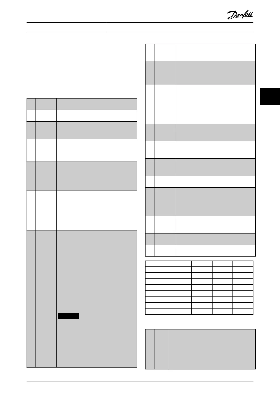
All digital inputs can be programmed to these functions:
[0] No
operation
No reaction to signals transmitted to the
terminal.
[1] Reset Resets frequency converter after a trip/alarm.
Not all alarms can be reset.
[2] Coast
inverse
(Default digital input 27): Coast stop, inverted
input (NC). The frequency converter leaves the
motor in free mode. Logic 0⇒coast stop.
[3] Coast and
reset
inverse
Reset and coast stop inverted input (NC).
Leaves motor in free mode and resets
frequency converter. Logic 0⇒coast stop and
reset.
[4] Quick stop
inverse
Inverted input (NC). Generates a stop in
accordance with quick stop ramp time set in
parameter 3-81 Quick Stop Ramp Time. When
the motor stops, the shaft is in free mode.
Logic 0⇒quick stop.
[5] DC brake
inverse
Inverted input for DC brake (NC). Stops motor
by energizing it with a DC current for a certain
time period. See parameter 2-01 DC Brake
Current to parameter 2-03 DC Brake Cut In Speed
[RPM]. The function is only active when the
value in parameter 2-02 DC Braking Time is
dierent from 0. Logic 0⇒DC brake.
[6] Stop
inverse
Stop inverted function. Generates a stop
function when the selected terminal goes from
logical level 1 to logical level 0.
The stop is performed according to the
selected ramp time:
•
Parameter 3-42 Ramp 1 Ramp Down
Time,
•
Parameter 3-52 Ramp 2 Ramp Down
Time,
•
Parameter 3-62 Ramp 3 Ramp down
Time, and
•
Parameter 3-72 Ramp 4 Ramp Down
Time.
NOTICE
When the frequency converter is at the
torque limit and has received a stop
command, it may not stop by itself. To
ensure that the frequency converter
stops, congure a digital output to [27]
Torque limit and stop. Connect this
digital output to a digital input that is
congured as coast.
[8] Start (Default digital input 18): Select start for a
start/stop command. Logic 1 = start,
logic 0 = stop.
[9] Latched
start
If a pulse is applied for minimum 2 ms, the
motor starts. The motor stops when stop
inverse is activated, or a reset command (via
DI) is given.
[10] Reversing (Default digital input 19). Change the direction
of motor shaft rotation. Select logic 1 to
reverse. The reversing signal only changes the
direction of rotation. It does not activate the
start function. Select both directions in
parameter 4-10 Motor Speed Direction. The
function is not active in process closed loop.
[11] Start
reversing
Used for start/stop and for reversing on the
same wire. Signals on start are not allowed at
the same time.
[12] Enable
start
forward
Disengages the counterclockwise movement
and allows clockwise direction.
[13] Enable
start
reverse
Disengages the clockwise movement and
allows counterclockwise direction.
[14] Jog (Default digital input 29): Activate jog speed.
See parameter 3-11 Jog Speed [Hz].
[15] Preset
reference
on
Shifts between external reference and preset
reference. It is assumed that [1] External/preset
has been selected in parameter 3-04 Reference
Function. Logic 0 = external reference active;
logic 1 = 1 of the 8 preset references is active.
[16] Preset ref
bit 0
Preset reference bit 0, 1, and 2 enable a choice
between 1 of the 8 preset references according
to Table 4.9.
[17] Preset ref
bit 1
Same as [16] Preset ref bit 0.
[18] Preset ref
bit 2
Same as [16] Preset ref bit 0.
Preset ref. bit 2 1 0
Preset ref. 0 0 0 0
Preset ref. 1 0 0 1
Preset ref. 2 0 1 0
Preset ref. 3 0 1 1
Preset ref. 4 1 0 0
Preset ref. 5 1 0 1
Preset ref. 6 1 1 0
Preset ref. 7 1 1 1
Table 4.9 Preset Reference Bit
[19] Freeze
ref
Freezes the actual reference, which is now the
point of enable/condition to be used for [21] Speed
up and [22] Speed down. If speed up/speed down
is used, the speed change always follows ramp 2
(parameter 3-51 Ramp 2 Ramp Up Time and
parameter 3-52 Ramp 2 Ramp Down Time) in the
range 0–parameter 3-03 Maximum Reference.
Parameter Descriptions Programming Guide
MG06J202 Danfoss A/S © 03/2019 All rights reserved. 67
4 4
 Loading...


