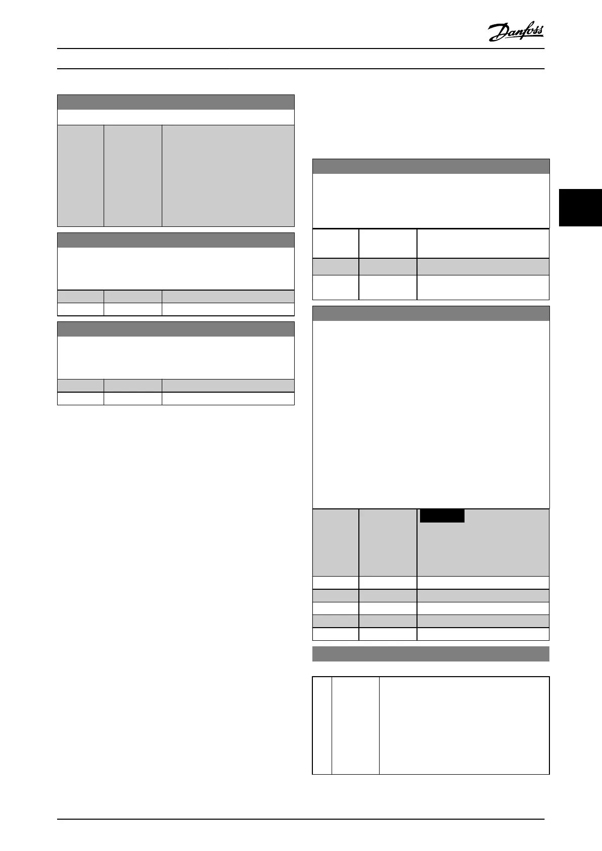
7-57 Process PID Fb. Filter Time
Range: Function:
0.001 s* [0.001 - 1 s] Set a time constant for the
feedback rst-order low-pass lter.
The low-pass lter improves steady-
state performance and dampens
oscillations on the reference/
feedback signals. However, severe
ltering can be detrimental to
dynamic performance.
7-60 Feedback 1 Conversion
Select a conversion for the feedback 1 signal. Select [0] Linear to
leave the feedback signal unchanged.
Option: Function:
[0] * Linear
[1] Square root
7-62 Feedback 2 Conversion
Select a conversion for the feedback 2 signal. Select [0] Linear to
leave the feedback signal unchanged.
Option: Function:
[0] * Linear
[1] Square root
4.9 Parameters: 8-** Communications and
Options
4.9.1 8-0* General Settings
8-01 Control Site
The setting in this parameter overrides the settings in
parameter 8-50 Coasting Select to parameter 8-56 Preset Reference
Select.
Option: Function:
[0] Digital and
ctrl.word
Use both digital input and control
word.
[1] Digital only Use digital inputs only.
[2] Controlword
only
Use control word only.
8-02 Control Word Source
Select the source of the control word: 1 of 2 serial interfaces or 4
installed options. During initial power-up, the frequency
converter automatically sets this parameter to [3] Option A if it
detects a valid eldbus option installed in slot A. When the
option is removed, the frequency converter detects a congu-
ration change, sets parameter 8-02 Control Word Source to default
setting [1] FC RS485, and trips. If an option is installed after initial
power-up, the setting of parameter 8-02 Control Word Source does
not change, but the frequency converter trips and shows: Alarm
67, Option Changed.
When retrotting a bus option into a frequency converter that
did not have a bus option installed earlier, change the control to
bus-based. This change is required for safety reasons to avoid an
unintended change.
Option: Function:
NOTICE
This parameter cannot be
adjusted while the motor is
running.
[0] None
[1] FC RS485
[2] FC USB
[3] Option A
[30] External Can
8-03 Control Word Timeout Time
Range: Function:
1 s* [0.1 -
18000.0 s]
Enter the maximum time expected to pass
between the reception of 2 consecutive
telegrams. If this time is exceeded, it indicates
that the serial communication has stopped.
The function selected in
parameter 8-04 Control Word Timeout Function
is then carried out. A valid control word
triggers the timeout counter.
Parameter Descriptions Programming Guide
MG06J202 Danfoss A/S © 03/2019 All rights reserved. 93
4 4

 Loading...


