1.3 Electrical Wiring - Control Cables
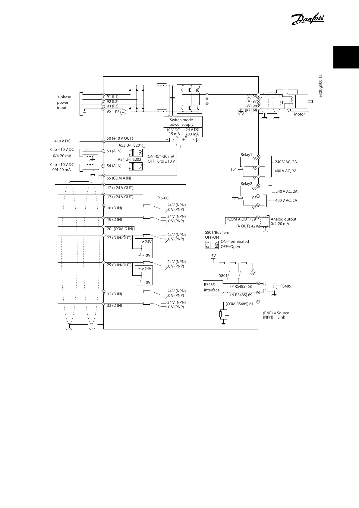
Illustration 1.2 Basic Wiring Schematic Drawing
A=Analog, D=Digital
Very long control cables and analog signals may in rare cases, and depending on installation, result in 50/60 Hz ground
loops due to noise from mains supply cables.
If 50/60 Hz ground loops occur, consider breaking the shield or insert a 100 nF capacitor between shield and enclosure.
To avoid ground currents from both groups to aect other groups, connect the digital and analog inputs and outputs
separately to the common inputs (terminals 20, 55, and 39) of the frequency converter. For example, switching on the digital
input may disturb the analog input signal.
Introduction Programming Guide
MG06J202 Danfoss A/S © 03/2019 All rights reserved. 7
1 1

 Loading...


