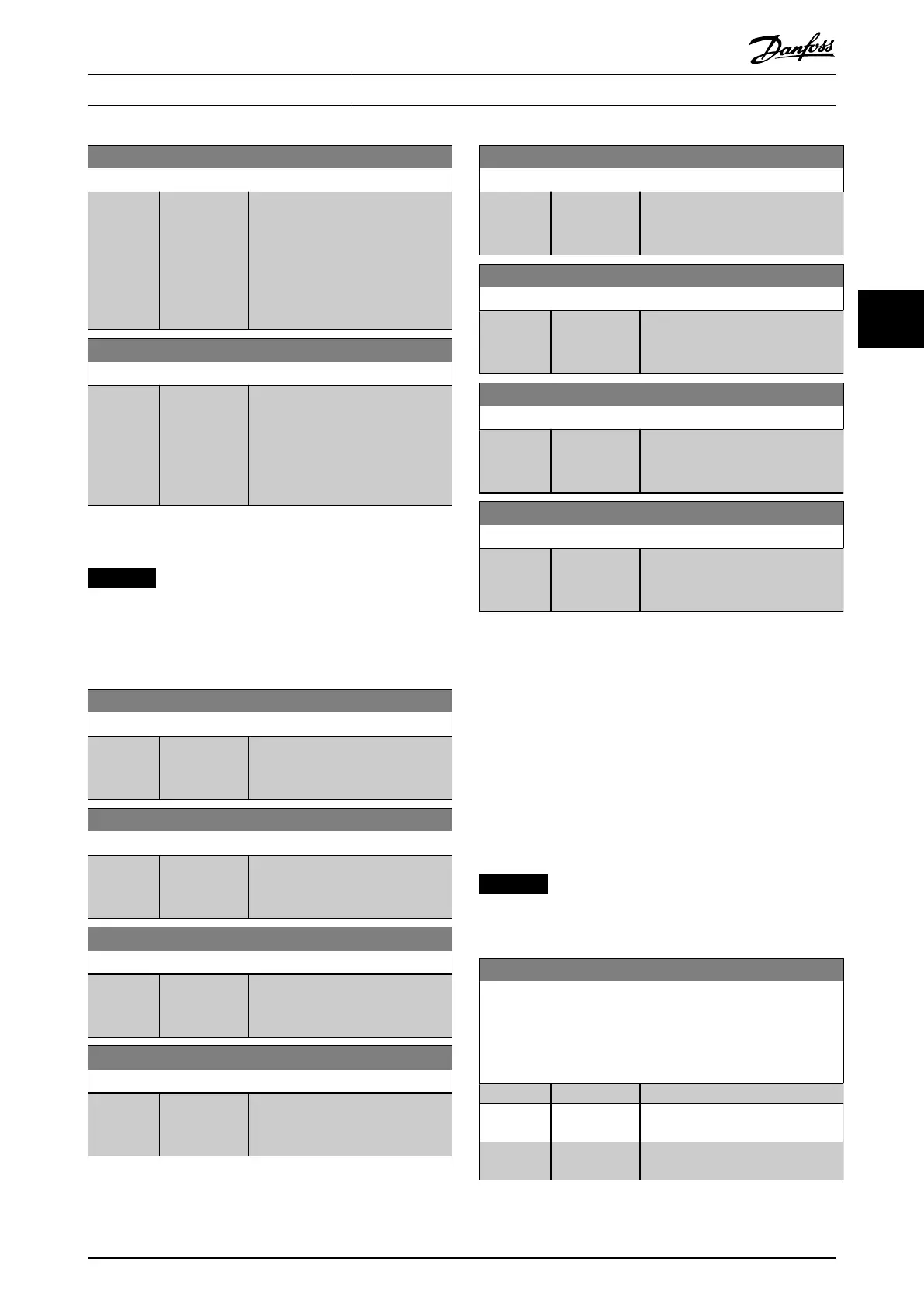
16-86 FC Port REF 1
Range: Function:
0* [-200 - 200 ] View the 2-byte status word (STW)
sent to the eldbus master.
Interpretation of the status word
depends on the eldbus option
installed and the control word
prole selected in
parameter 8-10 Control Prole.
16-87 Bus Readout Alarm/Warning
Range: Function:
0* [0 - 65535] Alarm and warning numbers in hex
as shown in the alarm log. The high
byte contains the alarm, the low
byte contains the warning. The
alarm number is the 1
st
one that
occurred after the last reset.
4.15.7 16-9* Diagnosis Readouts
NOTICE
When using MCT 10 Set-up Software, the readout
parameters can only be read online, that is as the actual
status. This means that the status is not stored in the
MCT 10 Set-up Software le.
16-90 Alarm Word
Range: Function:
0* [0 -
4294967295 ]
Show the alarm word sent via the
serial communication port in hex
code.
16-91 Alarm Word 2
Range: Function:
0* [0 -
4294967295]
View the alarm word sent via the
serial communication port in hex
code.
16-92 Warning Word
Range: Function:
0* [0 -
4294967295 ]
Show the warning word sent via
the serial communication port in
hex code.
16-93 Warning Word 2
Range: Function:
0* [0 -
4294967295]
View the warning word sent via the
serial communication port in hex
code.
16-94 Ext. Status Word
Range: Function:
0* [0 -
4294967295]
Returns the extended warning word
sent via the serial communication
port in hex code.
16-95 Ext. Status Word 2
Range: Function:
0* [0 -
4294967295 ]
Returns the extended status word 2
sent via the serial communication
port in hex code.
16-97 Alarm Word 3
Range: Function:
0* [0 -
4294967295 ]
Show the alarm word 3 sent via the
serial communication port in hex
code.
16-98 Warning Word 3
Range: Function:
0* [0 -
4294967295 ]
View the warning word sent via the
serial communication port in hex
code.
4.16 Parameters: 17-** Feedback
More parameters to congure the feedback from the
encoder (VLT
®
Encoder Input MCB 102), resolver (VLT
®
Resolver Input MCB 103), or the frequency converter itself.
4.16.1 17-1* Inc. Enc. Interface
Parameters in this group congure the incremental
interface of the VLT
®
Encoder Input MCB 102. Both the
incremental and absolute interfaces are active at the same
time.
NOTICE
These parameters cannot be adjusted while the motor is
running.
17-10 Signal Type
Select the incremental type (A/B channel) of the encoder in use.
Find the information on the encoder datasheet.
Select [0] None if the feedback sensor is an absolute encoder
only.
Option: Function:
[0] None
[1] * RS422 (5V
TTL)
[2] Sinusoidal
1Vpp
Parameter Descriptions Programming Guide
MG06J202 Danfoss A/S © 03/2019 All rights reserved. 149
4 4
 Loading...


