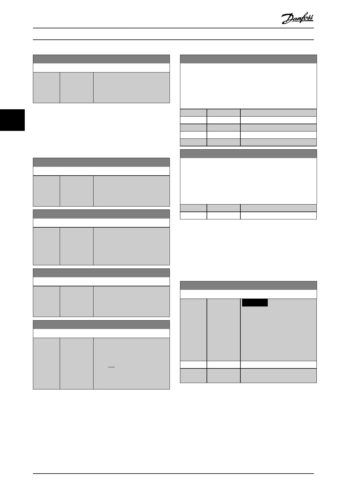
17-11 Resolution (PPR)
Range: Function:
1024* [10 - 10000] Enter the resolution of the
incremental track, that is the
number of pulses or periods per
revolution.
4.16.2 17-5* Resolver Interface
This parameter group is used for setting parameters for the
VLT
®
Resolver Input MCB 103.
Resolver parameters cannot be adjusted while the motor is
running.
17-50 Poles
Range: Function:
2* [2 - 8] Set the pole number on the
resolver.
The value is stated in the datasheet
for resolvers.
17-51 Input Voltage
Range: Function:
7 V* [2 - 8 V] Set the input voltage to the
resolver. The voltage is stated as
RMS value.
The value is stated in the datasheet
for resolvers.
17-52 Input Frequency
Range: Function:
10 kHz* [2 - 15 kHz] Set the input frequency to the
resolver.
The value is stated in the datasheet
for resolvers.
17-53 Transformation Ratio
Range: Function:
0.5* [0.1 - 1.1] Set the transformation ratio for the
resolver.
The transformation ratio is:
T
ratio
=
V
Out
V
In
The value is stated in the datasheet
for resolvers.
17-56 Encoder Sim. Resolution
Set the resolution and activate the encoder emulation function
(generation of encoder signals from the measured position from
a resolver). Use this function to transfer the speed or position
information from 1 frequency converter to another. To disable
the function, select [0] Disabled.
Option: Function:
[0] * Disabled
[1] 512
[2] 1024
[3] 2048
[4] 4096
17-59 Resolver Interface
Activate the VLT
®
Resolver Input MCB 103 when the resolver
parameters are selected.
To avoid damage to resolvers, adjust parameter 17-50 Poles and
parameter 17-53 Transformation Ratio before enabling this
parameter.
Option: Function:
[0] * Disabled
[1] Enabled
4.16.3 17-6* Monitoring and Application
This parameter group is for selecting extra functions when
VLT
®
Encoder Input MCB 102 or VLT
®
Resolver Input MCB
103 is tted into option slot B as speed feedback.
Monitoring and application parameters cannot be adjusted
while the motor is running.
17-60 Feedback Direction
Option: Function:
NOTICE
This parameter cannot be
adjusted while the motor is
running.
Change the detected encoder
rotation direction without changing
the wiring to the encoder.
[0] * Clockwise
[1] Counter
clockwise
Parameter Descriptions VLT® AutomationDrive FC 361
150 Danfoss A/S © 03/2019 All rights reserved. MG06J202
44
 Loading...


