4.14 Parameters: 15-** Drive Information
4.14.1 15-0* Operating Data
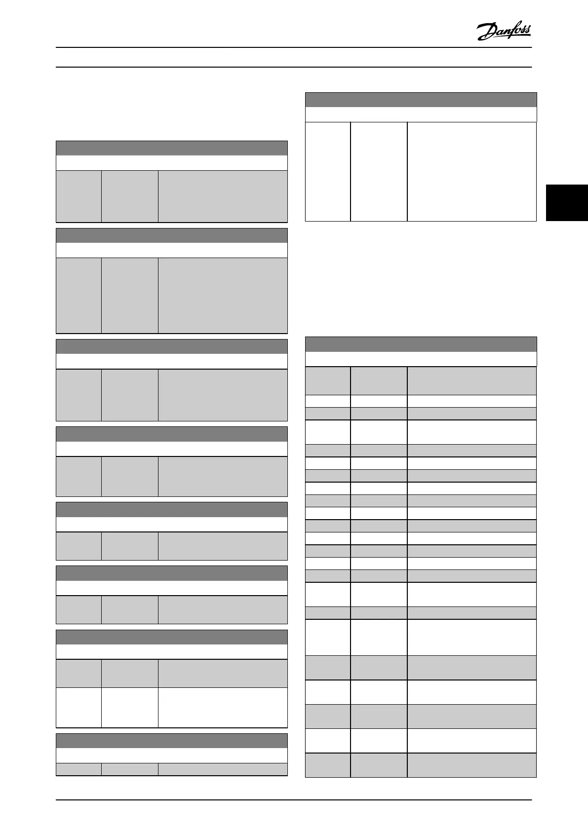
15-00 Operating hours
Range: Function:
0 h* [0 -
2147483647 h]
View how many hours the
frequency converter has run. The
value is saved when the frequency
converter is turned o.
15-01 Running Hours
Range: Function:
0 h* [0 -
2147483647 h]
View how many hours the motor
has run. Reset the counter in
parameter 15-07 Reset Running
Hours Counter. The value is saved
when the frequency converter is
turned o.
15-02 kWh Counter
Range: Function:
0 kWh* [0 -
2147483647
kWh]
Register the power consumption of
the motor as an average value over
1 hour. Reset the counter in
parameter 15-06 Reset kWh Counter.
15-03 Power Up's
Range: Function:
0* [0 -
2147483647 ]
View the number of times the
frequency converter has been
powered up.
15-04 Over Temp's
Range: Function:
0* [0 - 65535 ] View the number of frequency
converter temperature faults.
15-05 Over Volt's
Range: Function:
0* [0 - 65535 ] View the number of frequency
converter overvoltages.
15-06 Reset kWh Counter
Option: Function:
[0] * Do not reset No reset of the kWh counter is
required.
[1] Reset counter Press [OK] to reset the kWh counter
to 0 (see parameter 15-02 kWh
Counter).
15-07 Reset Running Hours Counter
Option: Function:
[0] * Do not reset
15-07 Reset Running Hours Counter
Option: Function:
[1] Reset counter To reset the running hours counter
to 0, select [1] Reset and press [OK]
(see parameter 15-01 Running
Hours). This parameter cannot be
selected via the serial port, RS485.
Select [0] Do not reset if no reset of
the running-hours counter is
required.
4.14.2 15-1* Data Log Settings
The data log enables continuous logging of up to 4 data
sources (parameter 15-10 Logging Source) at individual rates
(parameter 15-11 Logging Interval). A trigger event
(parameter 15-12 Trigger Event) and window
(parameter 15-14 Samples Before Trigger) are used to start
and stop the logging conditionally.
15-10 Logging Source
Option: Function:
Select which variables are to be
logged.
[0] * None
[1600] Control Word
[1601] Reference
[Unit]
[1602] Reference %
[1603] Status Word
[1610] Power [kW]
[1611] Power [hp]
[1612] Motor Voltage
[1613] Frequency
[1614] Motor current
[1616] Torque [Nm]
[1617] Speed [RPM]
[1618] Motor Thermal
[1620] Motor Angle
[1621] Torque [%]
High Res.
[1622] Torque [%]
[1624] Calibrated
Stator
Resistance
[1630] DC Link
Voltage
[1634] Heatsink
Temp.
[1635] Inverter
Thermal
[1645] Motor Phase U
Current
[1646] Motor Phase V
Current
Parameter Descriptions Programming Guide
MG06J202 Danfoss A/S © 03/2019 All rights reserved. 139
4 4
 Loading...


