3.1.2 Quick Transfer of Parameter Settings
between Multiple Frequency
Converters
Once the set-up of a frequency converter is complete,
store the data in the LCP or on a PC via MCT 10 Set-up
Software.
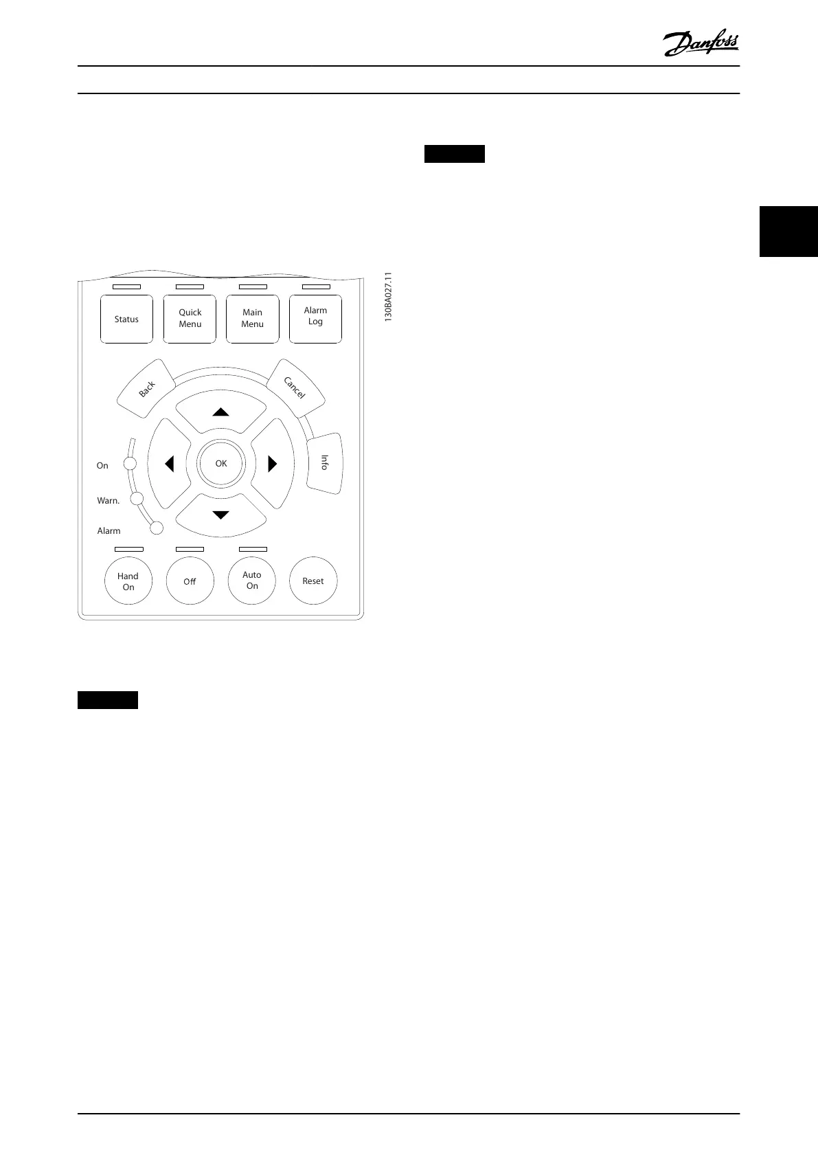
Illustration 3.9 LCP
Data storage in LCP
NOTICE
Stop the motor before performing this operation.
To store the data in the LCP:
1. Go to parameter 0-50 LCP Copy.
2. Press the [OK] key.
3. Select [1] All to LCP.
4. Press the [OK] key.
All parameter settings are now stored in the LCP indicated
by the progress bar. When 100% is reached, press [OK].
Connect the LCP to another frequency converter and copy
the parameter settings to this frequency converter as well.
Data transfer from LCP to frequency converter
NOTICE
Stop the motor before performing this operation.
To transfer the data from the LCP to the frequency
converter:
1. Go to parameter 0-50 LCP Copy.
2. Press the [OK] key.
3. Select [2] All from LCP.
4. Press the [OK] key.
The parameter settings stored in the LCP are now
transferred to the frequency converter indicated by the
progress bar. When 100% is reached, press [OK].
3.1.3 Display Mode
In normal operation, up to 5 dierent operating variables
can be indicated continuously in the middle section: 1.1,
1.2, and 1.3, as well as 2 and 3.
3.1.4 Display Mode - Selection of Readouts
It is possible to toggle between 3 status readout screens
by pressing [Status].
Operating variables with dierent formatting are shown in
each status view further in this section.
Table 3.1 shows the measurements that can be linked to
each of the operating variables. When options are
mounted, additional measurements are available.
Dene the links via
•
Parameter 0-20 Display Line 1.1 Small.
•
Parameter 0-21 Display Line 1.2 Small.
•
Parameter 0-22 Display Line 1.3 Small.
•
Parameter 0-23 Display Line 2 Large.
•
Parameter 0-24 Display Line 3 Large.
Each readout parameter selected in parameter 0-20 Display
Line 1.1 Small to parameter 0-24 Display Line 3 Large has its
own scale and digits after a possible decimal point. The
larger the numeric value of a parameter is, the fewer digits
are shown after the decimal point.
Example: Current readout 5.25 A, 15.2 A, 105 A.
Programming Programming Guide
MG06J202 Danfoss A/S © 03/2019 All rights reserved. 15
3 3

 Loading...


