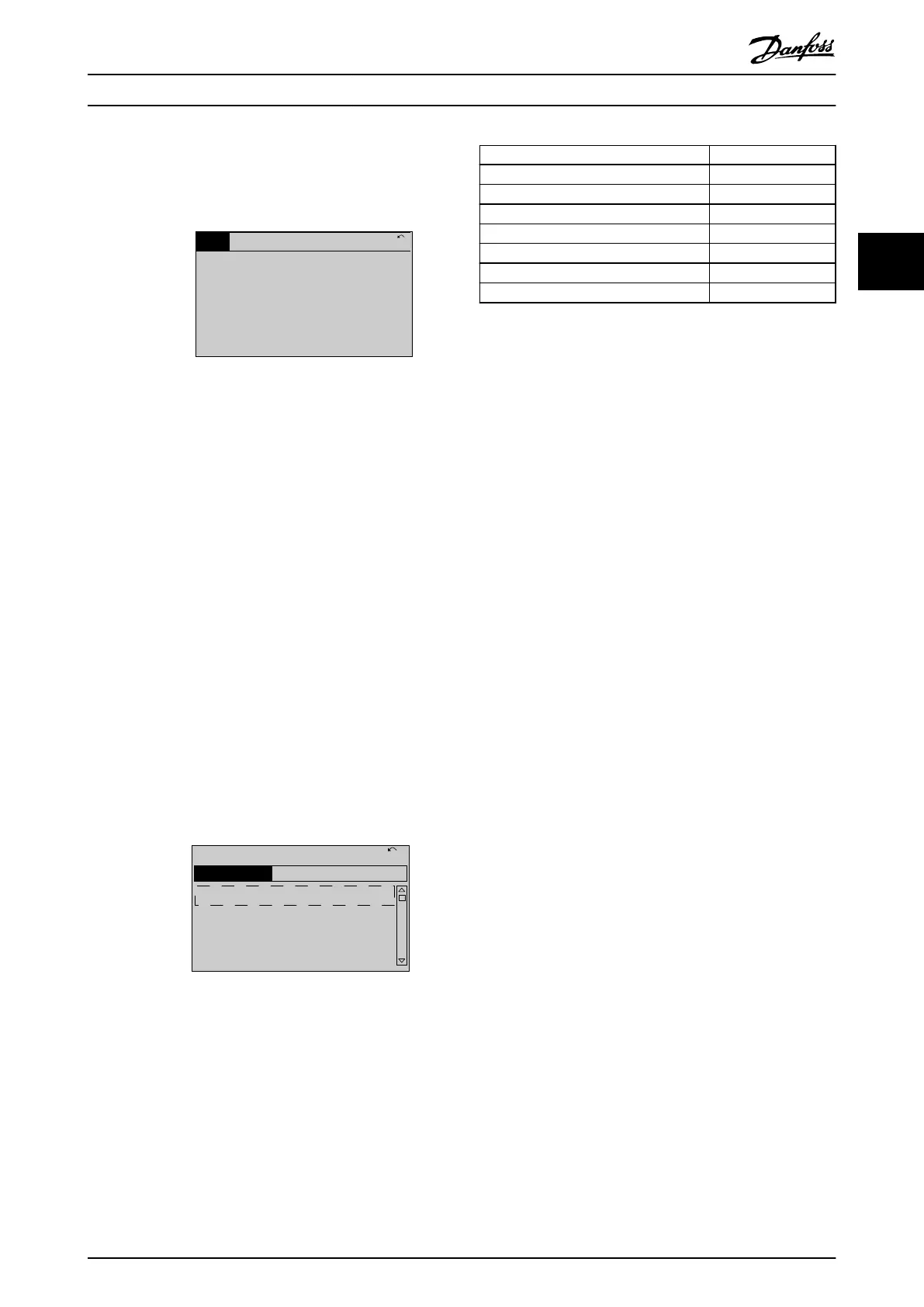
Status view III
This state shows the event and action of the smart logic
control. For further information, see
chapter 4.12 Parameters: 13-** Smart Logic Control.
130BP063.10
778 RPM
Auto Remote Running
1 (1)
4.0 kW0.86 A
State: 0 o 0 (o)
When: -
Do: -
Status
Illustration 3.12 Status View III
3.1.5 Parameter Set-up
The frequency converter can be used for practically all
assignments and oers 2 programming mode options:
•
Main menu mode.
•
Quick menu mode.
Main menu provides access to all parameters. Quick menu
takes the user through a few parameters, making it
possible to start operating the frequency converter.
Change a parameter in either main menu mode or quick
menu mode.
3.1.6 Quick Menu Key Functions
Press [Quick Menu] to enter a list of dierent areas
contained in the Quick Menu.
Select Q1 My Personal Menu to show the selected personal
parameters. These parameters are selected in
parameter 0-25 My Personal Menu. Up to 50 dierent
parameters can be added in this menu.
130BC916.10
Q1 My Personal Menu
Q2 Quick Setup
Q4 Smart Setup
Q5 Changes Made
0RPM 0.00A 1(1)
Quick Menus
Illustration 3.13 Quick Menus
Select Q2 Quick Setup to go through a selection of
parameters to get the motor running almost optimally. The
default settings for the other parameters consider the
required control functions and the conguration of signal
inputs/outputs (control terminals).
The parameter selection is eected with the navigation
keys. The parameters in Table 3.2 are accessible.
Parameter Setting
Parameter 0-01 Language
Parameter 1-20 Motor Power [kW] [kW]
Parameter 1-22 Motor Voltage [V]
Parameter 1-23 Motor Frequency [Hz]
Parameter 1-24 Motor Current [A]
Parameter 1-25 Motor Nominal Speed [RPM]
Parameter 3-02 Minimum Reference [RPM]
Table 3.2 Selection of Parameter
1) If terminal 27 is set to [0] No function, no connection to +24 V on
terminal 27 is necessary.
Select Changes made to get information about:
•
The last 10 changes. Use the [
▲
] [
▼
] navigation
keys to scroll between the last 10 changed
parameters.
•
The changes made since default setting.
Select Loggings to get information about the shown line
readouts. The information is shown as graphs.
Only parameters selected in parameter 0-20 Display Line 1.1
Small and parameter 0-24 Display Line 3 Large can be
viewed. It is possible to store up to 120 samples in the
memory for later reference.
Programming Programming Guide
MG06J202 Danfoss A/S © 03/2019 All rights reserved. 17
3 3

 Loading...


