3-01 Reference/Feedback Unit
Option: Function:
[172] in WG
[173] ft WG
[180] HP
3-02 Minimum Reference
Range: Function:
Size
related*
[ -999999.999
- par. 3-03
Reference-
FeedbackUnit]
Enter the minimum reference. The
minimum reference is the lowest
value obtainable by summing all
references.
Minimum reference is active only
when parameter 3-00 Reference
Range is set to [0] Min.- Max.
The minimum reference unit
matches the unit selected in
parameter 3-01 Reference/Feedback
Unit.
3-03 Maximum Reference
Range: Function:
Size
related*
[ par. 3-02 -
999999.999
Reference-
FeedbackUnit]
Enter the maximum reference. The
maximum reference is the highest
value obtainable by summing all
references.
The maximum reference unit
matches the unit selected in
parameter 3-00 Reference Range.
3-04 Reference Function
Option: Function:
[0] Sum Sums both external and preset
reference sources.
[1] External/Preset Use either the preset or the
external reference source.
Shift between external and preset
via a command or a digital input.
4.4.2 3-1* References
Select the preset references. Select Preset ref. bit 0/1/2 [16],
[17], or [18] for the corresponding digital inputs in
parameter group 5-1* Digital Inputs.
3-10 Preset Reference
Array [8]
Range: 0-7
Range: Function:
0 %* [-100 -
100 %]
Enter up to 8 dierent preset
references (0–7) in this parameter,
using array programming. The
preset reference is stated as a
percentage of the value Ref
MAX
3-10 Preset Reference
Array [8]
Range: 0-7
Range: Function:
(parameter 3-03 Maximum
Reference). If a Ref
MIN
dierent from
0 (parameter 3-02 Minimum
Reference) is programmed, the
preset reference is calculated as a
percentage of the full reference
range, that is on the basis of the
dierence between Ref
MAX
and
Ref
MIN
. Afterwards, the value is
added to Ref
MIN
. When using preset
references, select preset reference
bit 0/1/2 [16], [17] or [18] for the
corresponding digital inputs in
parameter group 5-1* Digital Inputs.
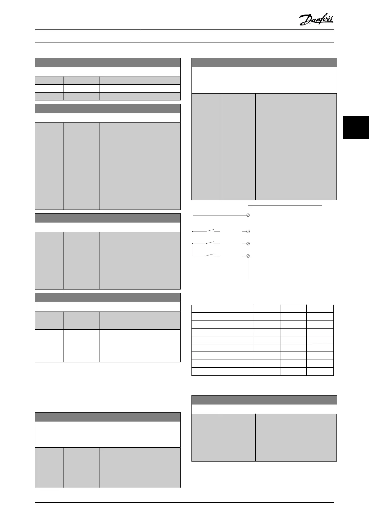
[P 5-13=Preset ref. bit 0]
Preset
[P 5-14=Preset ref. bit 1]
[P 5-15=Preset ref. bit 2]
10101010
76543210
29
12
(+24V)
11001100
32
11110000
33
130BA149.10
Illustration 4.14 Preset Reference
Preset ref. bit 2 1 0
Preset ref. 0 0 0 0
Preset ref. 1 0 0 1
Preset ref. 2 0 1 0
Preset ref. 3 0 1 1
Preset ref. 4 1 0 0
Preset ref. 5 1 0 1
Preset ref. 6 1 1 0
Preset ref. 7 1 1 1
Table 4.6 Preset Reference Bits
3-11 Jog Speed [Hz]
Range: Function:
Size
related*
[ 0 - par. 4-14
Hz]
The jog speed is a xed output
speed at which the frequency
converter is running when the jog
function is activated.
See also parameter 3-80 Jog Ramp
Time.
Parameter Descriptions Programming Guide
MG06J202 Danfoss A/S © 03/2019 All rights reserved. 51
4 4
 Loading...


