3-12 Catch up/slow Down Value
Range: Function:
0 %* [0 - 100 %] Enter a percentage (relative) value
to be either added to or deducted
from the actual reference for catch
up or slow down. If catch up is
selected via 1 of the digital inputs
(parameter 5-10 Terminal 18 Digital
Input to parameter 5-15 Terminal 33
Digital Input), the percentage
(relative) value is added to the total
reference. If slow down is selected
via 1 of the digital inputs
(parameter 5-10 Terminal 18 Digital
Input to parameter 5-15 Terminal 33
Digital Input), the percentage
(relative) value is deducted from
the total reference. Obtain
extended functionality with the
DigiPot function. See parameter
group 3-9* Digital Potentiometer.
3-13 Reference Site
Option: Function:
Select which reference site to activate.
[0] * Linked to
Hand / Auto
Use local reference when in hand-on mode,
or remote reference when in auto-on mode.
[1] Remote Use remote reference in both hand-on mode
and auto-on mode.
[2] Local Use local reference in both hand-on mode
and auto-on mode.
NOTICE
When set to [2] Local, the frequency
converter starts with this setting again
after a power-down.
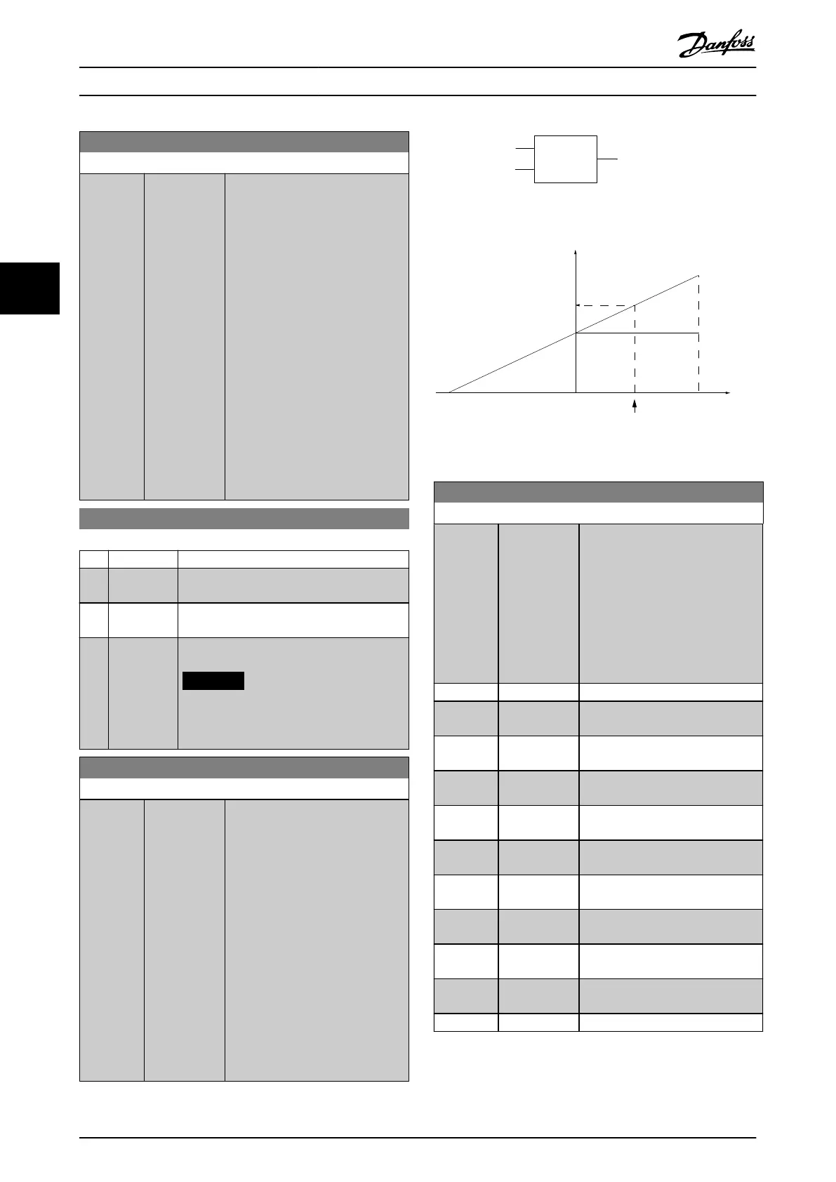
3-14 Preset Relative Reference
Range: Function:
0 %* [-200 -
200 %]
The actual reference, X, is increased
or decreased with the percentage Y,
set in parameter 3-14 Preset Relative
Reference.
This results in the actual reference
Z. Actual reference (X) is the sum of
the inputs selected in:
•
Parameter 3-15 Reference 1
Source.
•
Parameter 3-16 Reference 2
Source.
•
Parameter 3-17 Reference 3
Source.
•
Parameter 8-02 Control
Source.
Relative
Z=X+X*Y/100
Resulting
actual
reference
Y
X
130BA059.12
Z
Illustration 4.15 Preset Relative Reference
X
100
%
0-100
Z
Y
X+X*Y/100
P 3-14
130BA278.10
Illustration 4.16 Actual Reference
3-15 Reference Resource 1
Option: Function:
Select the reference input to be
used for the 1
st
reference signal.
Parameter 3-15 Reference Resource 1,
parameter 3-16 Reference Resource 2,
and parameter 3-17 Reference
Resource 3 dene up to 3 dierent
reference signals. The sum of these
reference signals denes the actual
reference.
[0] No function
[1] * Analog Input
53
[2] Analog Input
54
[7] Frequency
input 29
[8] Frequency
input 33
[11] Local bus
reference
Reference from terminals 68 and 69.
[20] Digital
pot.meter
[21] Analog input
X30/11
VLT
®
General Purpose I/O MCB 101
[22] Analog input
X30/12
VLT
®
General Purpose I/O MCB 101
[30] Option
Reference
[32] Bus PCD
Parameter Descriptions VLT® AutomationDrive FC 361
52 Danfoss A/S © 03/2019 All rights reserved. MG06J202
44
 Loading...


