3-16 Reference Resource 2
Option: Function:
Select the reference input to be
used for the 2
nd
reference signal.
Parameter 3-15 Reference Resource 1,
parameter 3-16 Reference Resource 2,
and parameter 3-17 Reference
Resource 3 dene up to 3 dierent
reference signals. The sum of these
reference signals denes the actual
reference.
[0] No function
[1] Analog Input
53
[2] Analog Input
54
[7] Frequency
input 29
[8] Frequency
input 33
[11] Local bus
reference
Reference from terminals 68 and 69.
[20] Digital
pot.meter
[21] Analog input
X30/11
[22] Analog input
X30/12
[32] Bus PCD
3-17 Reference Resource 3
Option: Function:
Select the reference input to be
used for the 3
rd
reference signal.
Parameter 3-15 Reference Resource 1,
parameter 3-16 Reference Resource 2,
and parameter 3-17 Reference
Resource 3 dene up to 3 dierent
reference signals. The sum of these
reference signals denes the actual
reference.
[0] No function
[1] Analog Input
53
[2] Analog Input
54
[7] Frequency
input 29
[8] Frequency
input 33
[11] Local bus
reference
Reference from terminals 68 and 69.
[20] Digital
pot.meter
3-17 Reference Resource 3
Option: Function:
[21] Analog input
X30/11
[22] Analog input
X30/12
[32] Bus PCD
3-18 Relative Scaling Reference Resource
Option: Function:
NOTICE
This parameter cannot be
adjusted while the motor is
running.
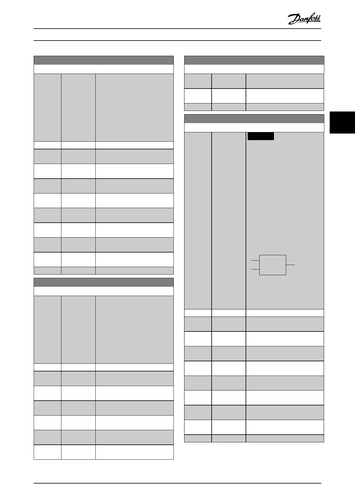
Select a variable value to be added
to the xed value (dened in
parameter 3-14 Preset Relative
Reference). The sum of the xed
and variable values (labeled Y in
Illustration 4.17) is multiplied by the
actual reference (labeled X in
Illustration 4.17). This product is
then added to the actual reference
(X+X*Y/100) to give the resulting
actual reference.
Relative
Z=X+X*Y/100
Resulting
actual
reference
Y
X
130BA059.12
Z
Illustration 4.17 Resulting Actual
Reference
[0] * No function
[1] Analog Input
53
[2] Analog Input
54
[7] Frequency
input 29
[8] Frequency
input 33
[11] Local bus
reference
Reference from terminals 68 and 69.
[20] Digital
pot.meter
[21] Analog input
X30/11
[22] Analog input
X30/12
[32] Bus PCD
Parameter Descriptions Programming Guide
MG06J202 Danfoss A/S © 03/2019 All rights reserved. 53
4 4
 Loading...


