14-90 Fault Level
This is an array parameter with 26 elements. Each of the bits can
be congured to any of the following options. Use this
parameter to customize fault levels.
Option: Function:
[2] Trip Changing a fault level from default
option [3] Trip Lock to [2] Trip leads
to the automatic reset of the alarm.
For alarms involving overcurrent,
the frequency converter has a
hardware protection that issues a 3-
minute recovery after 2 consecutive
overcurrent incidents. This hardware
protection cannot be overruled.
[3] Trip Lock
14-90 Fault Level
This is an array parameter with 26 elements. Each of the bits can
be congured to any of the following options. Use this
parameter to customize fault levels.
Option: Function:
[4] Trip w.
delayed reset
This option adds a delay between
automatic resets, otherwise it is the
same as option [2] Trip. The delay
prevents a situation where reset is
attempted repeatedly for an
overcurrent situation. Hardware
protection of the frequency
converter forces the 3-minute
recovery time after 2 consecutive
overcurrents (within a short time
window).
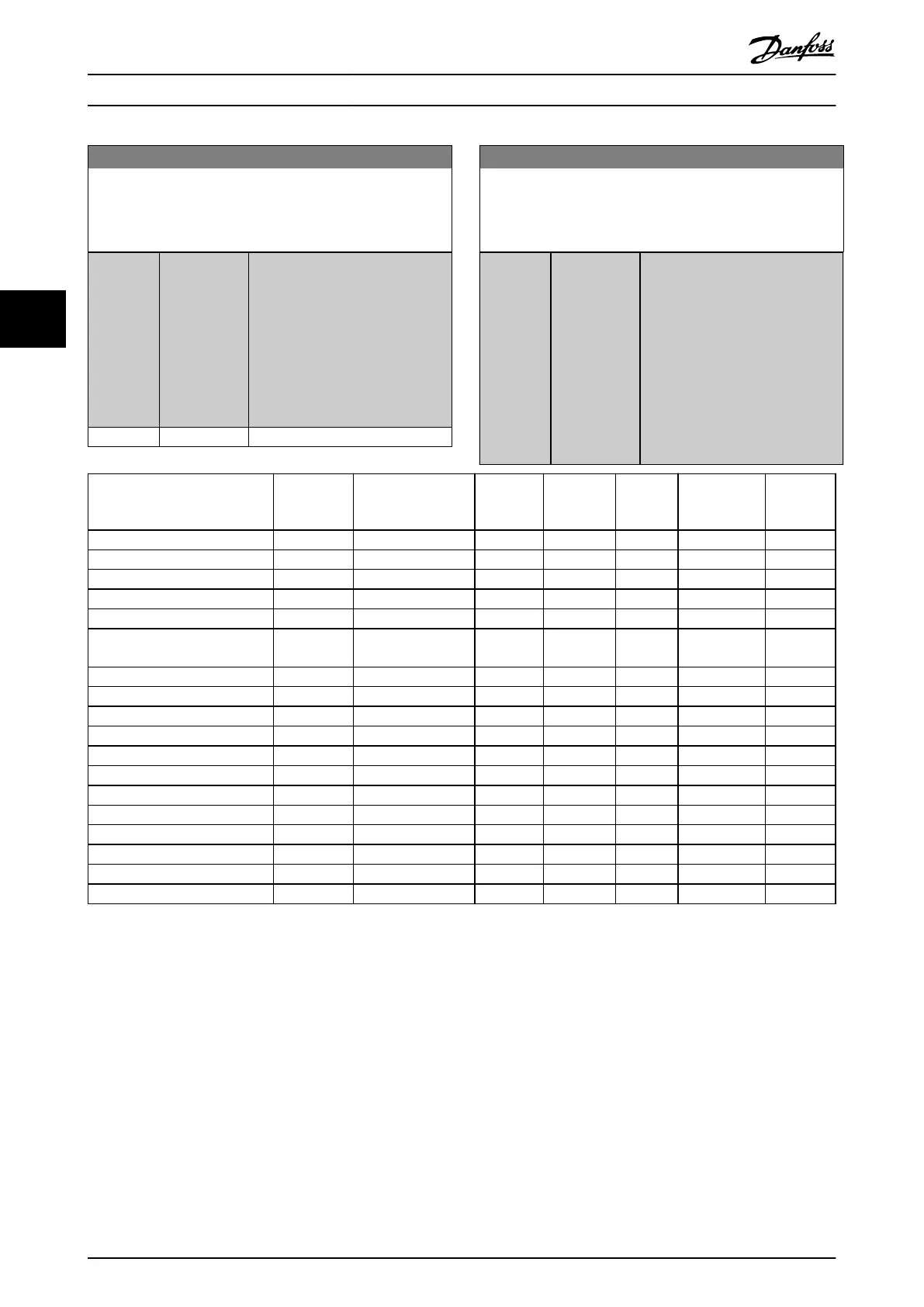
Failure Alarm Element in
parameter 14-90 Fau
lt Level
O Warning Trip Trip Lock Trip with
delayed
reset
10 V low 1 1490.0 X D – – –
24 V low 47 1490.1 X – – D –
1.8 V supply low 48 1490.2 X – – D –
Voltage limit 64 1490.3 X D – – –
Ground fault during ramping 14 1490.4 – – D X –
Ground fault 2 during cont.
operation
45 1490.5 – – D X –
Torque limit 12 1490.6 X D – – –
Overcurrent 13 1490.7 – – X D –
Short circuit 16 1490.8 – – X D –
Heat sink temperature 29 1490.9 – – X D –
Heat sink sensor 39 1490.10 – – X D –
Control card temperature 65 1490.11 – – X D –
Power card temperature 69 1490.12 – – X D –
Heat sink temperature 244 1490.13 – – X D –
Heat sink sensor 245 1490.14 – – X D –
Power card temperature 247 1490.15 – – X D –
Motor phase missing 30–32 1490.16 – – X D –
Locked rotor 99 1490.20 – – D X –
Table 4.18 Selection of Action when Selected Alarm Appears
MCT 10 Set-up Software has the element numbers listed in the column ID. Use this table together with MCT 10 Set-up Software to get information
about specic fault levels.
D stands for the default setting.
X stands for a possible option.
Parameter Descriptions VLT® AutomationDrive FC 361
138 Danfoss A/S © 03/2019 All rights reserved. MG06J202
44
 Loading...


