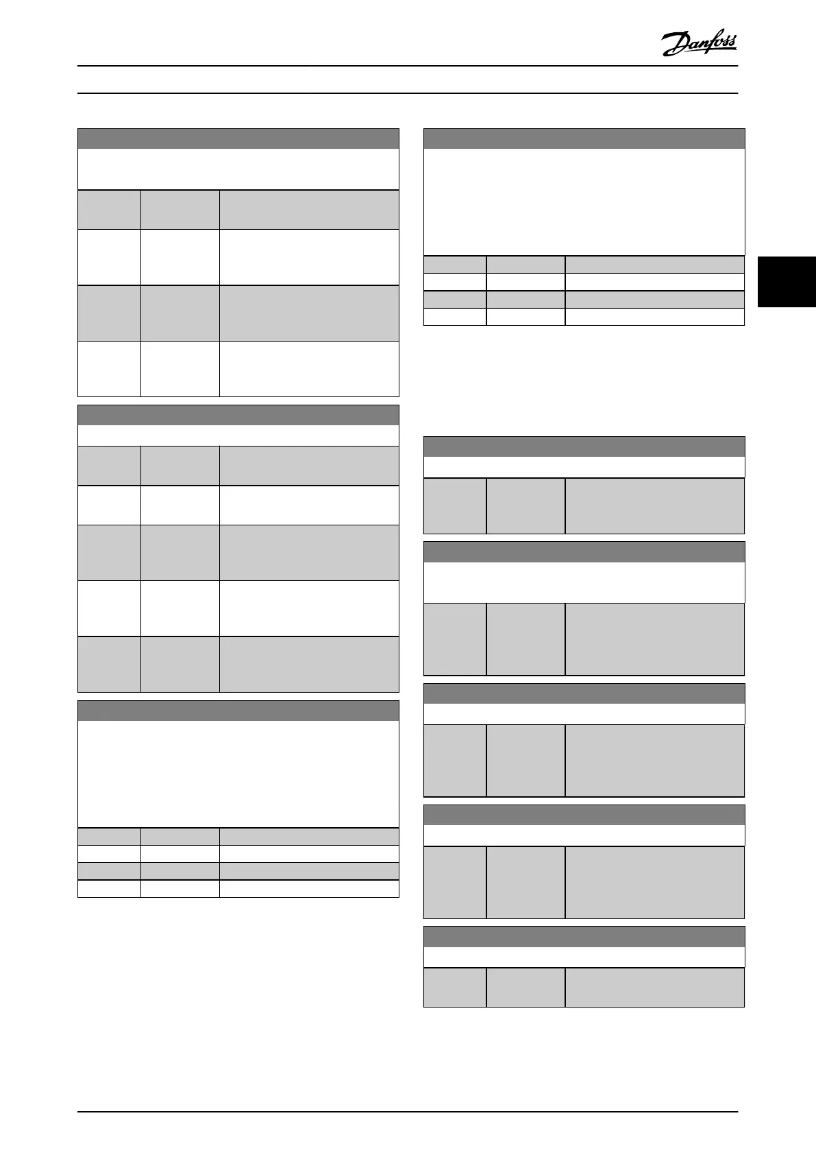
8-55 Set-up Select
Select the trigger for the set-up selection.
Option: Function:
[0] Digital input A digital input triggers the set-up
selection.
[1] Bus A serial communication port or the
eldbus triggers the set-up
selection.
[2] Logic AND The eldbus/serial communication
port and a digital input trigger the
set-up selection.
[3] * Logic OR The eldbus/serial communication
port or a digital input triggers the
set-up selection.
8-56 Preset Reference Select
Option: Function:
Select the trigger for the preset
reference selection.
[0] Digital input A digital input triggers the preset
reference selection.
[1] Bus A serial communication port or the
eldbus triggers the preset
reference selection.
[2] Logic AND The eldbus/serial communication
port and a digital input trigger the
preset reference selection.
[3] * Logic OR The eldbus/serial communication
port or a digital input triggers the
preset reference selection.
8-57 Prodrive OFF2 Select
Select control of the frequency converter OFF2 selection via the
terminals (digital input) and/or via the eldbus. This parameter is
active only when parameter 8-01 Control Site is set to [0] Digital
and ctrl. word and parameter 8-10 Control Word Prole is set to [1]
PROFIdrive prole.
Option: Function:
[0] Digital input
[1] Bus
[2] Logic AND
[3] * Logic OR
8-58 Prodrive OFF3 Select
Select control of the frequency converter OFF3 selection via the
terminals (digital input) and/or via the eldbus. This parameter is
active only when parameter 8-01 Control Site is set to [0] Digital
and ctrl. word, and parameter 8-10 Control Word Prole is set to
[1] PROFIdrive prole.
Option: Function:
[0] Digital input
[1] Bus
[2] Logic AND
[3] * Logic OR
4.9.6 8-8* FC Port Diagnostics
These parameters are used for monitoring the bus
communication via the frequency converter RS485 port
terminals 68-69.
8-80 Bus Message Count
Range: Function:
0* [0 - 0 ] This parameter shows the number
of valid telegrams detected on the
bus.
8-81 Bus Error Count
Array [6]
Range: Function:
0* [0 - 0 ] This parameter shows the number
of telegrams with faults (for
example CRC fault) detected on the
bus.
8-82 Slave Messages Rcvd
Range: Function:
0* [0 - 0 ] This parameter shows the number
of valid telegrams addressed to the
slave sent by the frequency
converter.
8-83 Slave Error Count
Range: Function:
0* [0 - 0 ] This parameter shows the number
of error telegrams, which are not
executed by the frequency
converter.
8-84 Slave Messages Sent
Range: Function:
0* [0 - 0 ] This parameter shows the number
of messages sent from the slave.
Parameter Descriptions Programming Guide
MG06J202 Danfoss A/S © 03/2019 All rights reserved. 103
4 4
 Loading...


