[20] Freeze
output
Freezes the actual motor frequency (Hz), which is
now the point of enable/condition to be used for
[21] Speed up and [22] Speed down. If speed up/
speed down is used, the speed change always
follows ramp 2 (parameter 3-51 Ramp 2 Ramp Up
Time and parameter 3-52 Ramp 2 Ramp Down Time)
in the range 0–parameter 1-23 Motor Frequency.
NOTICE
When freeze output is active, the frequency
converter cannot be stopped via a low [8]
Start signal. Stop the frequency converter
via a terminal programmed for [2] Coasting
inverse or [3] Coast and reset inverse.
[21] Speed
up
Select [21] Speed up and [22] Speed down for digital
control of the up/down speed (motor potenti-
ometer). Activate this function by selecting either
[19] Freeze ref or [20] Freeze output. When speed
up/speed down is activated for less than 400 ms,
the resulting reference is increased/decreased by
0.1%. If speed up/speed down is activated for
more than 400 ms, the resulting reference follows
the setting in ramping up/down parameters 3-
x1/3-x2.
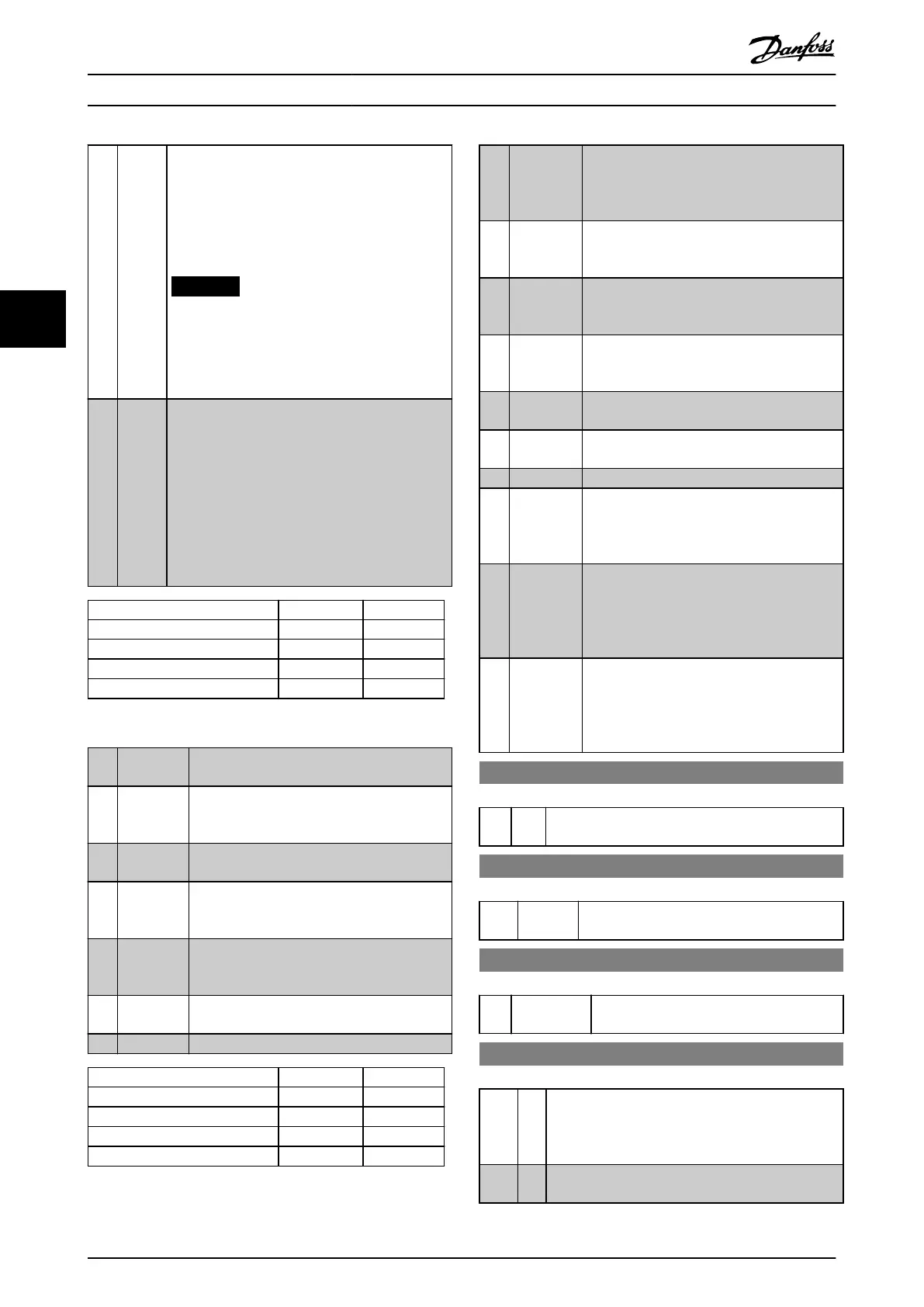
Shut down Catch up
Unchanged speed 0 0
Reduced by %-value 1 0
Increased by %-value 0 1
Reduced by %-value 1 1
Table 4.10 Shut Down/Catch Up
[22] Speed
down
Same as [21] Speed up.
[23] Set-up
select bit 0
Select [23] Set-up select bit 0 or select [24] Set-
up select bit 1 to select 1 of the 4 set-ups. Set
parameter 0-10 Active Set-up to Multi Set-up.
[24] Set-up
select bit 1
(Default digital input 32): Same as [23] Set-up
select bit 0.
[28] Catch up Increases reference value by percentage
(relative) set in parameter 3-12 Catch up/slow
Down Value.
[29] Slow down Reduces reference value by percentage
(relative) set in parameter 3-12 Catch up/slow
Down Value.
[34] Ramp bit 0 Enables a selection between 1 of the 4 ramps
available, according to Table 4.11.
[35] Ramp bit 1 Same as [34] Ramp bit 0.
Preset ramp bit 1 0
Ramp 1 0 0
Ramp 2 0 1
Ramp 3 1 0
Ramp 4 1 1
Table 4.11 Preset Ramp Bit
[51] External
interlock
This function makes it possible to give an
external fault to the frequency converter. This
fault is treated in the same way as an
internally generated alarm.
[55] DigiPot
Increase
Increase signal to the digital potentiometer
function described in parameter group 3-9*
Digital Pot. Meter.
[56] DigiPot
Decrease
Decrease signal to the digital potentiometer
function described in parameter group 3-9*
Digital Pot. Meter.
[57] DigiPot
Clear
Clears the digital potentiometer reference
described in parameter group 3-9* Digital Pot.
Meter.
[62] Reset
Counter A
Input for reset of counter A.
[65] Reset
Counter B
Input for reset of counter B.
[66] Sleep Mode
[72] PID error
inverse
When enabled, this option inverts the
resulting error from the process PID controller.
Available only if parameter 1-00 Conguration
Mode is set to [7] Extended PID Speed OL.
[73] PID reset I-
part
When enabled, this option resets the I-part of
the process PID controller. Equivalent to
parameter 7-40 Process PID I-part Reset.
Available only if parameter 1-00 Conguration
Mode is set to [7] Extended PID Speed OL.
[74] PID enable Enables the extended process PID controller.
Equivalent to parameter 7-50 Process PID
Extended PID. Available only if
parameter 1-00 Conguration Mode is set to [7]
Extended PID Speed OL.
5-10 Terminal 18 Digital Input
Option: Function:
[8] * Start Functions are described in parameter group 5-1*
Digital Inputs.
5-11 Terminal 19 Digital Input
Option: Function:
[10] * Reversing Functions are described in parameter group
5-1* Digital Inputs.
5–12 Terminal 27 Digital Input
Option: Function:
[2] * Coast inverse Functions are described in parameter group
5-1* Digital Inputs.
5-13 Terminal 29 Digital Input
Option: Function:
Select the function from the available digital input
range and the additional options [60] Counter A, [61]
Counter A, [63] Counter B, and [64] Counter B.
Counters are used in smart logic control functions.
[14] * Jog Functions are described in parameter group 5-1*
Digital Inputs.
Parameter Descriptions VLT® AutomationDrive FC 361
68 Danfoss A/S © 03/2019 All rights reserved. MG06J202
44
 Loading...


