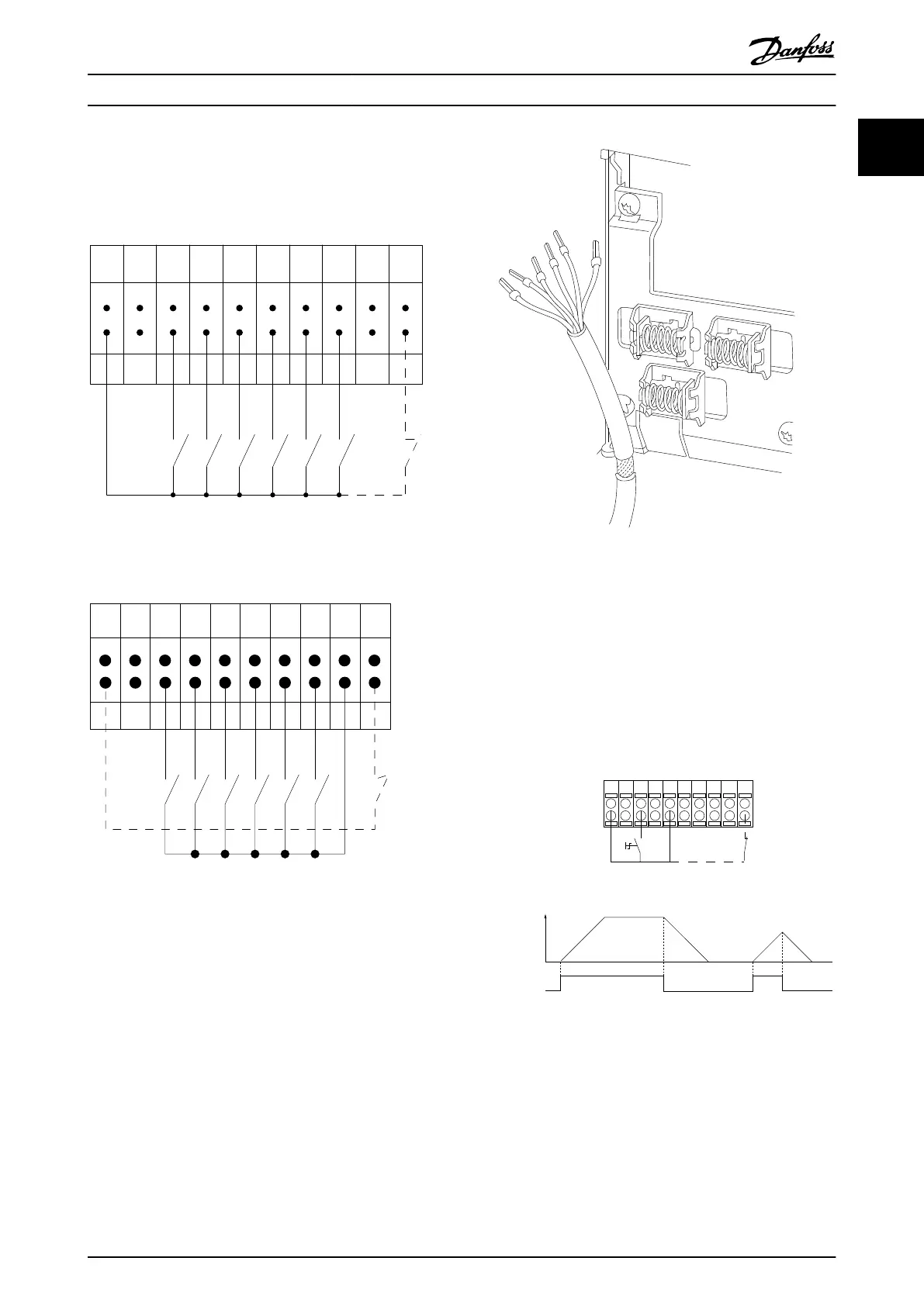
Input polarity of control terminals
12 13 18 19 27 29 32 33 20 37
+24 VDC
0 VDC
130BT106.10
PNP (Source)
Digital input wiring
Illustration 1.3
NPN (Sink)
Digital input wiring
12 13 18 19 27 29 32 33 20 37
+24 VDC
0 VDC
130BT107.11
Illustration 1.4
NOTE
Control
cables must be screened/armoured.
See section entitled Earthing
of Screened/Armoured Control
Cables for the correct termination of control cables.
Illustration 1.5
1.1.6 Start/Stop
Terminal 18 = 5-10
Terminal 18 Digital Input [8] Start
Terminal 27 = 5-12 Terminal 27 Digital Input [0] No
operation (Default coast inverse)
Terminal 37 = Safe stop (where available)
12 13 18 37
130BA155.12
322719 29 33 20
P 5-12 [0]
P 5-10 [8]
Start/Stop
+24V
Speed
Safe Stop
Start/Stop
[18]
Illustration 1.6
Introduction
VLT
®
Refrigeration Drive Programming Guide
MG16H102 - VLT
®
is a registered Danfoss trademark
9
1 1

 Loading...


