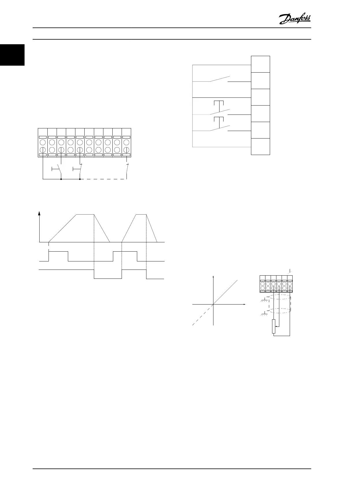
1.1.7 Pulse Start/Stop
Terminal 18 = 5-10
Terminal 18 Digital InputLatched start,
[9]
Terminal 27= 5-12 Terminal 27 Digital InputStop inverse, [6]
Terminal 37 = Safe stop (where available)
12 13 18 37
130BA156.12
322719 29 33 20
P 5 - 12 [6]
P 5 - 10[9]
+24V
Speed
Start Stop inverse Safe Stop
Start (18)
Start (27)
Illustration 1.7
1.1.8 Speed Up/Down
Terminals 29/32 = Speed up/down
Terminal
18 = 5-10 Terminal 18 Digital Input Start
[9] (default)
Terminal 27 = 5-12 Terminal 27 Digital Input
Freeze reference [19]
Terminal 29 = 5-13 Terminal 29 Digital Input
Speed up [21]
Terminal 32 = 5-14 Terminal 32 Digital Input
Speed down [22]
NOTE
Terminal
29 only in FC x02 (x=series type).
12
18
27
29
32
37
+24V
Par. 5-10
Par. 5-12
Par. 5-13
Par. 5-14
130BA021.12
Illustration 1.8
1.1.9 Potentiometer Reference
Voltage reference via a potentiometer
Reference
Source 1 = [1] Analog input 53 (default)
Terminal 53, Low Voltage = 0 V
Terminal 53, High Voltage = 10 V
Terminal 53, Low Ref./Feedback = 0 RPM
Terminal 53, High Ref./Feedback = 1500 RPM
Switch S201 = OFF (U)
130BA154.11
555039 42 53 54
Speed RPM
P 6-15
1 kΩ
+10V/30mA
Ref. voltage
P 6-11 10V
Illustration 1.9
Introduction
VLT
®
Refrigeration Drive Programming Guide
10 MG16H102 - VLT
®
is a registered Danfoss trademark
11
 Loading...


