refrigerant pressure measurements into temperature
values.
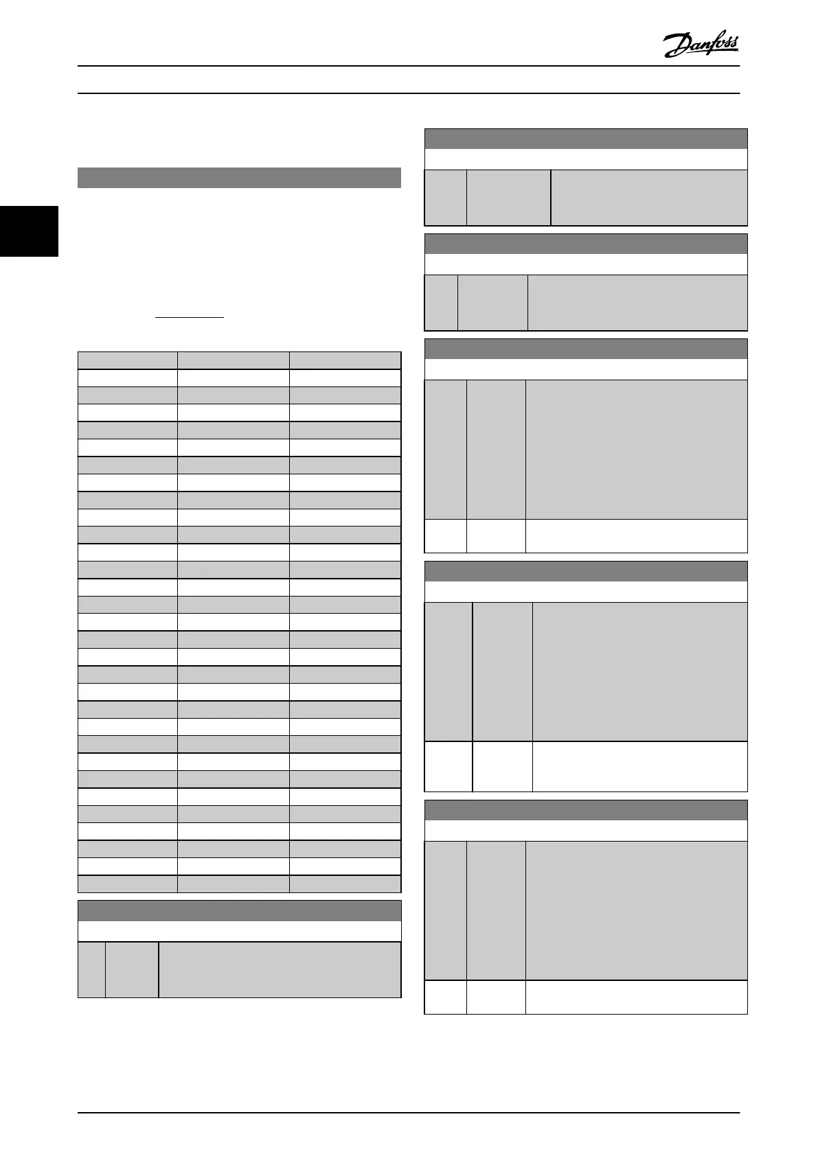
20-30 Refrigerant
Select the refrigerant used in the compressor application. This
parameter
must be specified correctly for the pressure to
temperature conversion to be accurate. If the refrigerant used is
not listed in choices [0] through [6], select User defined [7]. Then,
use 20-31 User Defined Refrigerant A1, 20-32 User Defined
Refrigerant A2 and 20-33 User Defined Refrigerant A3 to provide
A1, A2 and A3 for the equation below:
Temperature
=
A
2
(
ln
(
Pe
+ 1
)
−
A
1
)
−
A
3
Option: Function:
[0] * R user
[1] R12
[2] R22
[3] R134a
[4] R502
[5] R717
[6] R13
[7] R13b1
[8] R23
[9] R500
[10] R503
[11] R114
[12] R142b
[14] R32
[15] R227
[16] R401A
[17] R507
[18] R402A
[19] R404A
[20] R407C
[21] R407A
[22] R407B
[23] R410A
[24] R170
[25] R290
[26] R600
[27] R600a
[28] R744
[29] R1270
[30] R417A
[31] Isceon 29
20-31 User Defined Refrigerant A1
Range: Function:
10 * [8 - 12 ] Use this parameter to enter the value of
coefficient
A1 when 20-30 Refrigerant is set to
User defined [7].
20-32 User Defined Refrigerant A2
Range: Function:
-2250 * [-3000 -
-1500
]
Use this parameter to enter the value
of coefficient A2 when 20-30 Refrigerant
is set to User defined [7].
20-33 User Defined Refrigerant A3
Range: Function:
250 * [200 - 300 ] Use this parameter to enter the value of
coefficient
A3 when 20-30 Refrigerant is set
to User defined [7].
20-35 Fan 1 Area [in2]
Range: Function:
Used for setting the area of the air ducts in
connection
with feedback conversion
pressure/velocity to flow. The unit (in
2
) is
determined by the setting of 0-03 Regional
Settings. Fan 1 is used with feedback 1. In
case of flow difference control, set
20-20 Feedback Function to [1] Difference, if
flow fan 1 – flow fan 2 is to be controlled.
750
in2*
[0 -
15000 in2]
20-36 Fan 2 Area [m2]
Range: Function:
Used for setting the area of the air ducts in
connection
with feedback conversion
pressure/velocity to flow. The unit (m
2
) is
determined by the setting of 0-03 Regional
Settings. Fan 2 is used with feedback 2. In
case of flow difference control, set
20-20 Feedback Function to [1] Difference, if
flow fan 1 – flow fan 2 is to be controlled.
0.500
m2*
[0.000 -
10.000
m2]
20-37 Fan 2 Area [in2]
Range: Function:
Used for setting the area of the air ducts in
connection
with feedback conversion
pressure/velocity to flow. The unit (in
2
) is
determined by the setting of 0-03 Regional
Settings. Fan 2 is used with feedback 2. In
case of flow difference control, set
20-20 Feedback Function to [1] Difference, if
flow fan 1 – flow fan 2 is to be controlled.
750
in2*
[0 -
15000 in2]
Parameter Description
VLT
®
Refrigeration Drive Programming Guide
116 MG16H102 - VLT
®
is a registered Danfoss trademark
33
 Loading...


