The Function Setup parameters are grouped in the
following
way:
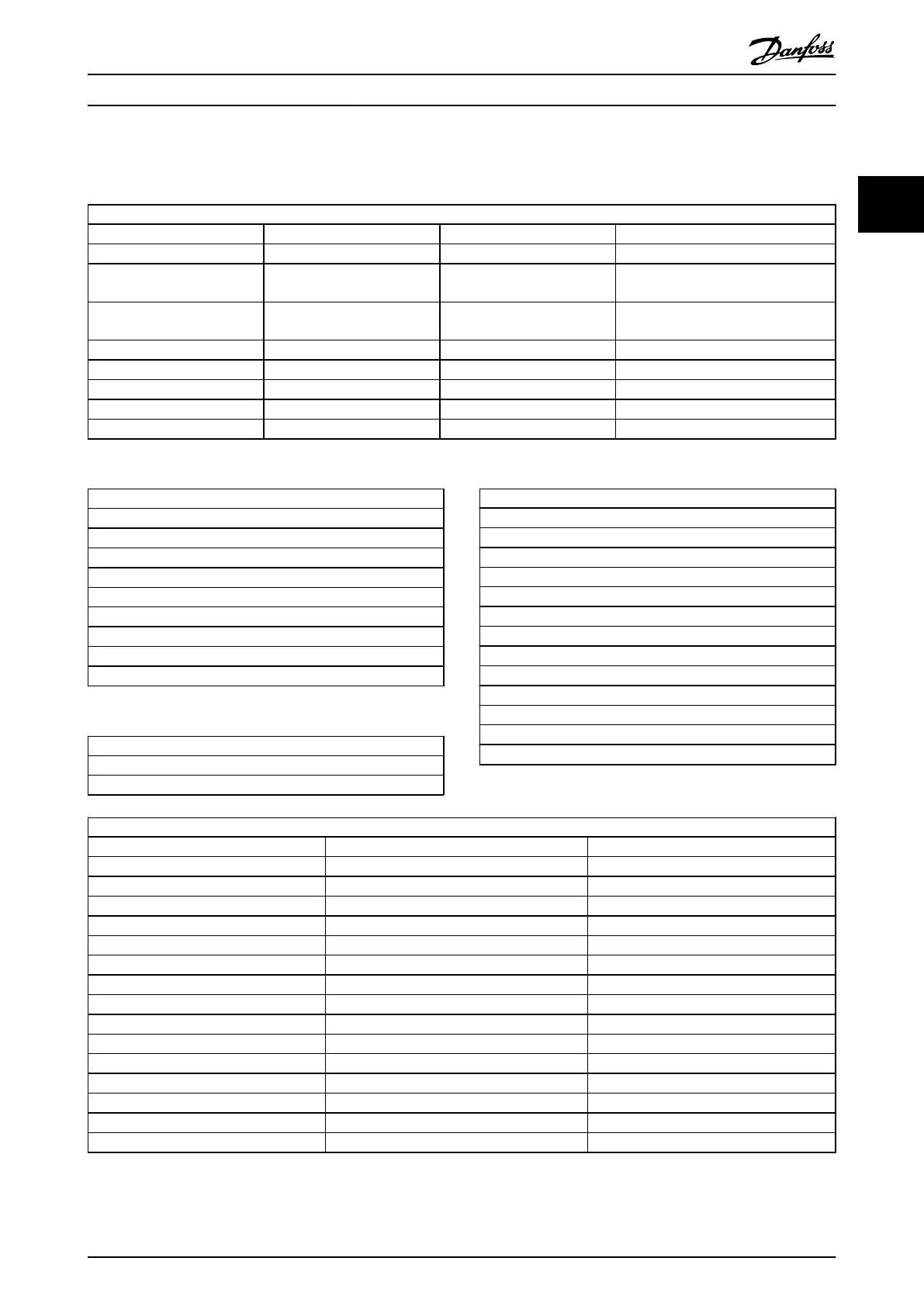
Q3-1 General Settings
Q3-10 Adv. Motor Settings Q3-11 Analog Output Q3-12 Clock Settings Q3-13 Display Settings
1-90 Motor Thermal Protection 6-50 Terminal 42 Output 0-70 Set date and time 0-20 Display Line 1.1 Small
1-93 Thermistor Source 6-51 Terminal 42 Output min.
scale
0-71 Date format 0-21 Display Line 1.2 Small
1-29 Automatic Motor
Adaption
6-52 Terminal 42 Output max.
scale
0-72 Time format 0-22 Display Line 1.3 Small
14-01 Switching Frequency 0-74 DST/Summertime 0-23 Display Line 2 large
0-76 DST/Summertime start 0-24 Display Line 3 large
0-77 DST/Summertime end 0-37 Display Text 1
0-38 Display Text 2
0-39 Display Text 3
Table 2.2
Q3-2 Open Loop Settings
1-00 Configuration Mode
3-02 Minimum Reference
3-03 Maximum reference
3-15 Reference 1 Source
6-10 Terminal 53 Low Voltage
6-11 Terminal 53 High Voltage
6-14 Terminal 53 Low Reference / Feedb. value
6-15 Terminal 53 High ref / Feed. value
3-10 Preset reference
Table 2.3
Q3-3 Closed Loop Settings
1-00 Configuration mode
20-00 Feedback 1 Source
Q3-3 Closed Loop Settings
20-12 Reference/Feedback Unit
6-20 Term 54 low voltage
6-21 Term 54 high voltage
6-22 Terminal 54 Low Current (only visible if switch set to I)
6-23 Terminal 54 High Current (only visible if switch set to I)
6-24 Terminal 54 Low ref / Feedb. value
6-25 Terminal 54 High ref / Feedb. value
3-02 Min. Reference
3-03 Max. Reference
20-21 Setpoint 1
20-93 PID Proportional Gain
20-94 PID Integral Time
3-13 Reference site
Table 2.4
Q3-4 Application Settings
Compressor Condenser Single fan/ pump
22-75 Short Cycle Protection 22-40 Minimum run time 22-40 Minimum run time
22-76 Interval between Starts 22-41 Minumum sleep time 22-41 Minumum sleep time
22-77 Minimum Run Time 22-42 Wake-up Speed [RPM] 22-42 Wake-up Speed [RPM]
20-00 Feedback 1 Source 22-43 Wake-up Speed [Hz] 22-43 Wake-up Speed [Hz]
20-01 Feedback 1 Conversion 22-44 Wake up ref. /FB difference 22-44 Wake up ref. /FB difference
20-02 Feedback 1 Source Unit 20-00 Feedback 1 Source
20-30 Refrigerant 20-01 Feedback 1 Conversion
20-40 ThermostatPressostat 20-02 Feedback 1 Source Unit
20-41 Cut-out value 20-30 Refrigerant
20-42 Cut-in value 20-40 ThermostatPressostat
25-00 Pack Controller 20-41 Cut-out value
25-06 Number of compressors 20-42 Cut-in value
25-20 Neutral zone
25-21 +zone
25-22 -zone
Table 2.5
How to Programme
VLT
®
Refrigeration Drive Programming Guide
MG16H102 - VLT
®
is a registered Danfoss trademark
21
2 2
 Loading...


