NOTE
•
For
the best adaptation of the frequency
converter, run AMA on a cold motor
•
AMA cannot be performed while the motor is
running
NOTE
Avoid
generating external torque during AMA.
NOTE
If
one of the settings in parameter group 1-2* Motor Data
is changed, 1-30 Stator Resistance (Rs) to 1-39 Motor Poles,
the advanced motor parameters, will return to default
setting.
This parameter cannot be adjusted while the motor is
running.
NOTE
Full
AMA should be run without filter only while reduced
AMA should be run with filter.
See section: Application
Examples > Automatic Motor
Adaptation in the Design Guide.
3.3.5 1-3* Adv. Motor Data
Parameters for advanced motor data. The motor data in
1-30
Stator Resistance (Rs) to 1-39 Motor Poles must match
the relevant motor in order to run the motor optimally.
The default settings are figures based on common motor
parameter values from normal standard motors. If the
motor parameters are not set correctly, a malfunction of
the frequency converter system may occur. If the motor
data is not known, running an AMA (Automatic Motor
Adaptation) is recommended. See the Automatic Motor
Adaptation section. The AMA sequence will adjust all
motor parameters except the moment of inertia of the
rotor and the iron loss resistance (1-36 Iron Loss Resistance
(Rfe)).
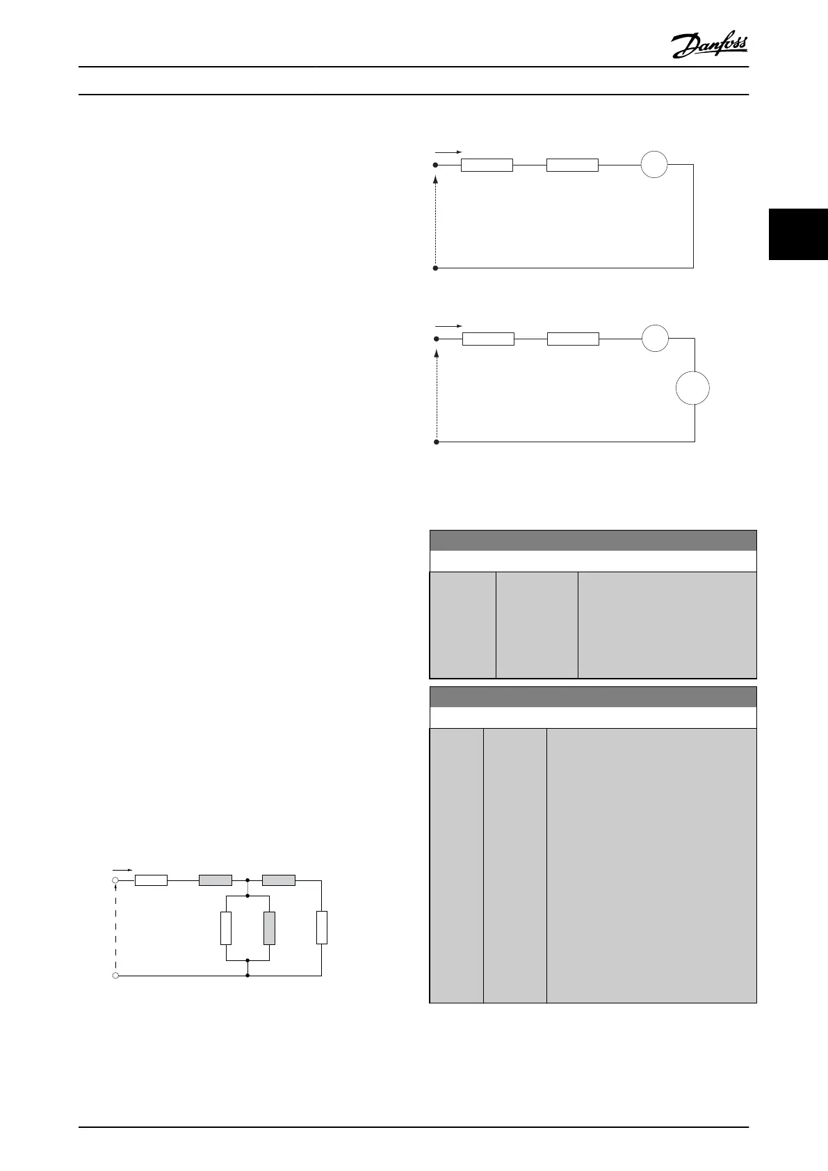
130BA375.11
R
S
P 1-30
R
1s
X
h
P1-35
R
1
X
2
X
1
U
1
I
1
Illustration 3.4 Motor Equivalent Diagram for an Asynchronous
Motor
I
d
R
s
Par. 1-30
L
d
Par. 1-37
ω
s
L
q
I
q
-
+
U
d
I
d
R
s
Par. 1-30
L
q
=L
d
Par. 1-37
ω
s
L
d
I
d
-
+
+
-
Par. 1-40
ω
s
λ
PM
U
q
d-axis equivalent circuit
q-axis equivalent circuit
130BC056.10
Illustration 3.5 Motor Equivalent Circuit Diagram for a PM Non
Salient
Motor
1-30 Stator Resistance (Rs)
Range: Function:
Size
related*
[ 0.0140 -
140.0000
Ohm]
Set the stator resistance value.
Enter the value from a motor data
sheet or perform an AMA on a
cold motor. This parameter cannot
be adjusted while the motor is
running.
1-31 Rotor Resistance (Rr)
Range: Function:
Size
related*
[ 0.0100
-
100.0000
Ohm]
Fine-tuning
R
r
will improve shaft
performance. Set the rotor resistance
value using one of these methods:
1. Run an AMA on a cold motor.
The frequency converter will
measure the value from the
motor. All compensations are
reset to 100%.
2. Enter the R
r
value manually.
Obtain the value from the
motor supplier.
3. Use the R
r
default setting. The
frequency converter establishes
the setting on the basis of the
motor nameplate data.
NOTE
1-31
Rotor Resistance (Rr) will not have effect when
1-10 Motor Construction = [1] PM, non salient SPM.
Parameter Description
VLT
®
Refrigeration Drive Programming Guide
MG16H102 - VLT
®
is a registered Danfoss trademark
39
3 3
 Loading...


