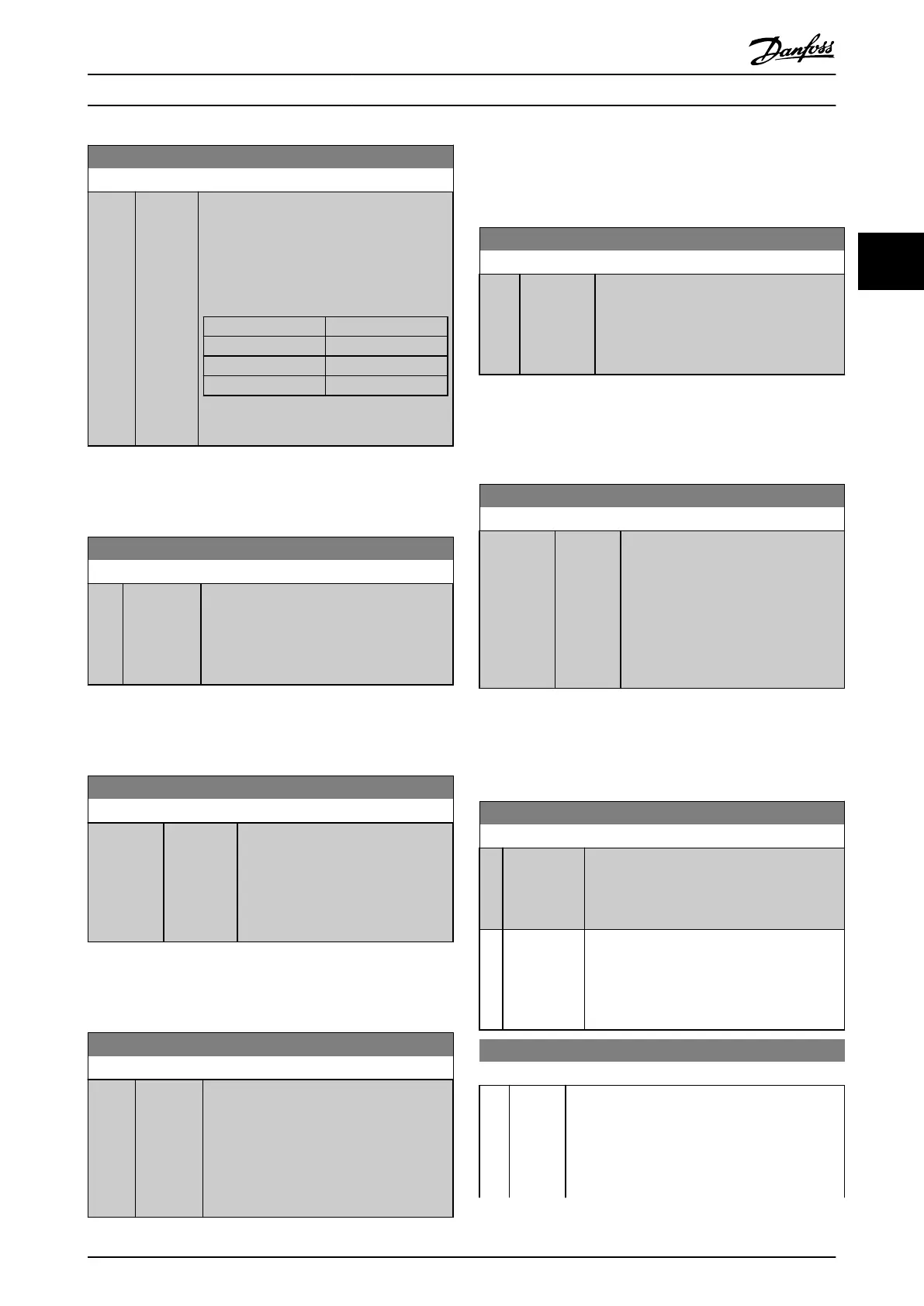
1-61 High Speed Load Compensation
Range: Function:
100 %* [0 - 300
%]
Enter the % value to compensate voltage in
relation
to load when the motor is running
at high speed and obtain the optimum U/f
characteristic. The motor size determines the
frequency range within which this parameter
is active.
Motor size [kW] Change-over [Hz]
0.25-7.5 > 10
11-45 < 5
55-550 < 3-4
Table 3.8
NOTE
1-61
High Speed Load Compensation will not have effect
when 1-10 Motor Construction = [1] PM, non salient SPM.
1-62 Slip Compensation
Range: Function:
0 %* [-500 - 500
%]
Enter the % value for slip compensation, to
compensate
for tolerances in the value of
n
M,N
. Slip compensation is calculated
automatically, i.e. on the basis of the rated
motor speed n
M,N
.
NOTE
1-62
Slip Compensation will not have effect when
1-10 Motor Construction = [1] PM, non salient SPM.
1-63 Slip Compensation Time Constant
Range: Function:
Size related* [0.05 - 5 s] Enter the slip compensation reaction
speed. A high value results in slow
reaction, and a low value results in
quick reaction. If low-frequency
resonance problems arise, use a
longer time setting.
NOTE
1-63
Slip Compensation Time Constant will not have effect
when 1-10 Motor Construction = [1] PM, non salient SPM.
1-64 Resonance Dampening
Range: Function:
100 %* [0 - 500
%]
Enter the resonance dampening value. Set
1-64
Resonance Dampening and
1-65 Resonance Dampening Time Constant to
help eliminate high-frequency resonance
problems. To reduce resonance oscillation,
increase the value of 1-64 Resonance
Dampening.
NOTE
1-64
Resonance Dampening will not have effect when
1-10 Motor Construction = [1] PM, non salient SPM.
1-65 Resonance Dampening Time Constant
Range: Function:
5 ms* [5 - 50 ms]
Set 1-64
Resonance Dampening
and
1-65 Resonance Dampening Time Constant to
help eliminate high-frequency resonance
problems. Enter the time constant that
provides the best dampening.
NOTE
1-65 Resonance Dampening Time Constant will not have
effect when 1-10 Motor Construction = [1] PM, non salient
SPM.
1-66 Min. Current at Low Speed
Range: Function:
Size related* [ 1 - 200
%]
Enter
the minimum motor current at
low speed.
Increasing this current improves
developed motor torque at low speed.
Low speed is here defined as speeds
below 6% of the Nominal Speed of
Motor (1-25 Motor Nominal Speed) in
VVC
plus
PM Control
NOTE
1-66
will not have affect if 1-10 =[0]
3.3.8 1-7* Start Adjustments
1-70 PM Start Mode
Option: Function:
[0] Rotor
Detection
Suitable for all applications where the motor
is
known to be standing still when starting
(e.g. conveyors, pumps and non wind milling
fans).
[1] Parking If the motor turns at a slight speed (i.e. lower
than
2-5% of the nominal speed) e.g. due to
fans with light wind milling, select [1] Parking
and adjust 2-06 Parking Current and
2-07 Parking Time accordingly.
1-71 Start Delay
Range: Function:
0 s* [0.0 -
120.0 s]
This parameter refers to the start function
selected in 1-72 Start Function.
Enter the time delay required before commencing
acceleration.
The parameter is also used for delayed start of
compressor functionality in Injection Control.
Parameter Description
VLT
®
Refrigeration Drive Programming Guide
MG16H102 - VLT
®
is a registered Danfoss trademark
43
3 3

 Loading...


