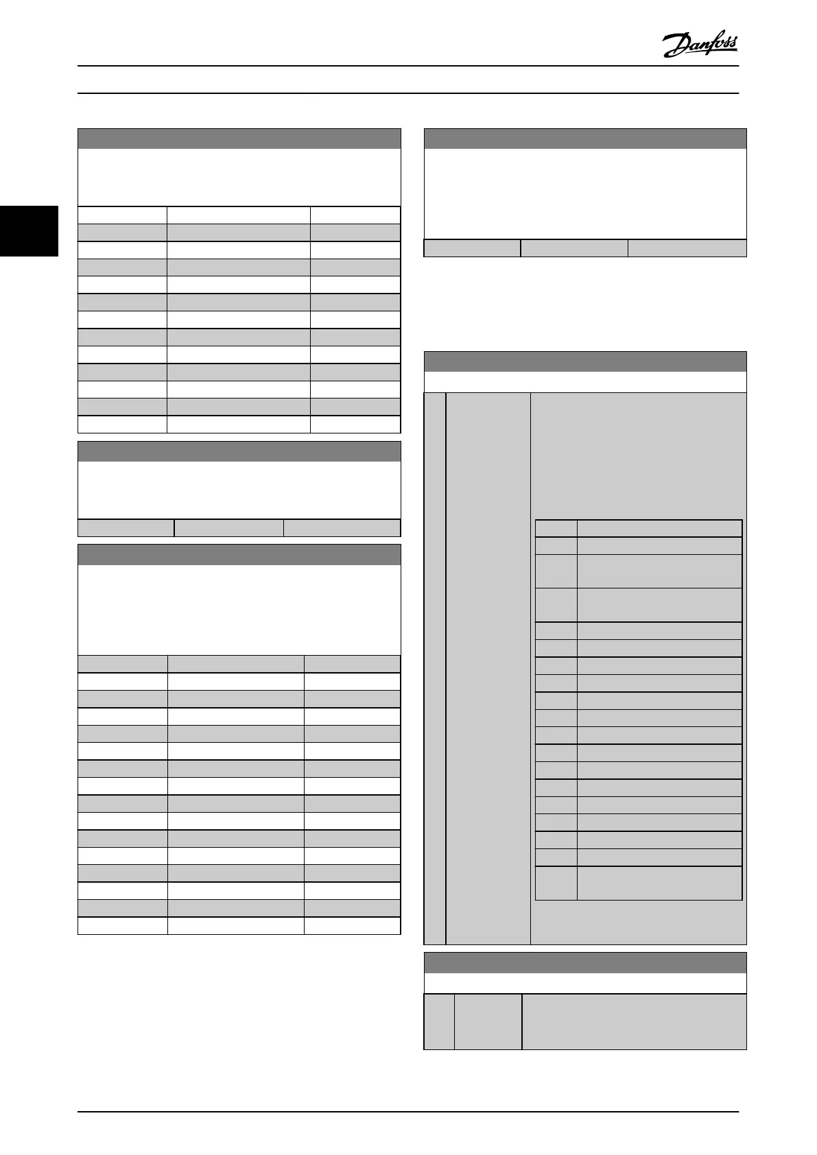
5-63 Terminal 29 Pulse Output Variable
Select the variable for viewing on the terminal 29 display. Same
options
and functions as parameter group 5-6*.
Option: Function:
[100] Output frequency
[101] Reference
[102] Feedback
[103] Motor Current
[104] Torque rel to limit
[105] Torq relate to rated
[106] Power
[107] Speed
[108] Torque
[109] Max Out Freq
[113] Ext. Closed Loop 1
[114] Ext. Closed Loop 2
[115] Ext. Closed Loop 3
5-65 Pulse Output Max Freq #29
Set the maximum frequency for terminal 29 corresponding to the
output
variable set in 5-63 Terminal 29 Pulse Output Variable.
Range: Function:
5000 Hz* [0 - 32000 Hz]
5-66 Terminal X30/6 Pulse Output Variable
Select the variable for read-out on terminal X30/6.
This
parameter is active when option module MCB 101 is
installed in the frequency converter.
Same options and functions as parameter group 5-6*.
Option: Function:
[0] * No operation
[45] Bus ctrl.
[48] Bus ctrl., timeout
[100] Output frequency
[101] Reference
[102] Feedback
[103] Motor Current
[104] Torque rel to limit
[105] Torq relate to rated
[106] Power
[107] Speed
[108] Torque
[109] Max Out Freq
[113] Ext. Closed Loop 1
[114] Ext. Closed Loop 2
[115] Ext. Closed Loop 3
NOTE
This
parameter cannot be adjusted while the motor is
running.
5-68 Pulse Output Max Freq #X30/6
Select the maximum frequency on terminal X30/6 referring to
the
output variable in 5-66 Terminal X30/6 Pulse Output Variable.
This parameter is active when option module MCB 101 is
mounted in the frequency converter.
Range: Function:
5000 Hz* [0 - 32000 Hz]
3.7.7 5-9* Bus Controlled
This parameter group selects digital and relay outputs via
a
fieldbus setting.
5-90 Digital & Relay Bus Control
Range: Function:
0 * [0 -
2147483647
]
This meter holds the state of the digital
outputs and relays that is controlled by
bus.
A logical '1' indicates that the output is
high or active.
A logical '0' indicates that the output is low
or inactive.
Bit 0 CC Digital Output Terminal 27
Bit 1 CC Digital Output Terminal 29
Bit 2 GPIO Digital Output Terminal X
30/6
Bit 3 GPIO Digital Output Terminal X
30/7
Bit 4 CC Relay 1 output terminal
Bit 5 CC Relay 2 output terminal
Bit 6 Option B Relay 1 output terminal
Bit 7 Option B Relay 2 output terminal
Bit 8 Option B Relay 3 output terminal
Bit 9-15 Reserved for future terminals
Bit 16 Option C Relay 1 output terminal
Bit 17 Option C Relay 2 output terminal
Bit 18 Option C Relay 3 output terminal
Bit 19 Option C Relay 4 output terminal
Bit 20 Option C Relay 5 output terminal
Bit 21 Option C Relay 6 output terminal
Bit 22 Option C Relay 7 output terminal
Bit 23 Option C Relay 8 output terminal
Bit
24-31
Reserved for future terminals
Table 3.14
5-93 Pulse Out #27 Bus Control
Range: Function:
0 %* [0 - 100 %] Contains the frequency to apply to the
digital
output terminal 27, when it is
configured as [Bus Controlled].
Parameter Description
VLT
®
Refrigeration Drive Programming Guide
70 MG16H102 - VLT
®
is a registered Danfoss trademark
33
 Loading...


