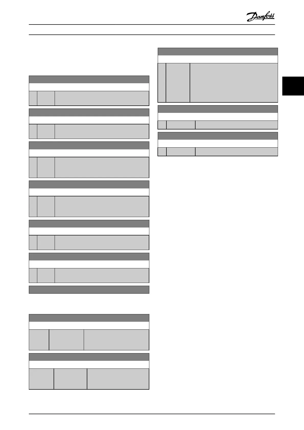
3.9.7 8-8* FC Port Diagnostics
These parameters are used for monitoring the Bus
communication
via the FC Port.
8-80 Bus Message Count
Range: Function:
0 * [0 - 0 ] This parameter shows the number of valid
telegrams
detected on the bus.
8-81 Bus Error Count
Range: Function:
0 * [0 - 0 ] This parameter shows the number of telegrams
with
faults (e.g. CRC fault), detected on the bus.
8-82 Slave Message Count
Range: Function:
0 * [0 - 0 ] This parameter shows the number of valid
telegrams
addressed to the slave, sent by the
frequency converter.
8-83 Slave Error Count
Range: Function:
0 * [0 - 0 ] This parameter shows the number of error
telegrams,
which could not be executed by the
frequency converter.
Range: Function:
0 * [0 - 0 ] This parameter shows the number of messages
sent from this frequency converter.
Range: Function:
0 * [0 - 0 ] This parameter shows the number of messages
suppressed
due to time-out.
3.9.8 8-9* Bus Jog
8-90 Bus Jog 1 Speed
Range: Function:
100 RPM* [ 0
- par. 4-13
RPM]
Enter
the jog speed. Activate this
fixed jog speed via the serial port
or fieldbus option.
8-91 Bus Jog 2 Speed
Range: Function:
Size related* [ 0 - par. 4-13
RPM]
Enter
the jog speed. Activate this
fixed jog speed via the serial
port or fieldbus option.
8-94 Bus Feedback 1
Range: Function:
0 * [-200 -
200
]
Write a feedback to this parameter via the
serial communication port or fieldbus option.
This parameter must be selected in
20-00 Feedback 1 Source, 20-03 Feedback 2
Source or 20-06 Feedback 3 Source as a feedback
source.
8-95 Bus Feedback 2
Range: Function:
0 * [-200 - 200 ]
See 8-94 Bus Feedback 1
for further details.
8-96 Bus Feedback 3
Range: Function:
0 * [-200 - 200 ]
See 8-94 Bus Feedback 1
for further details.
Parameter Description
VLT
®
Refrigeration Drive Programming Guide
MG16H102 - VLT
®
is a registered Danfoss trademark
83
3 3
 Loading...


