1.21.0 1.4
30
10
20
100
60
40
50
1.81.6 2.0
2000
500
200
400
300
1000
600
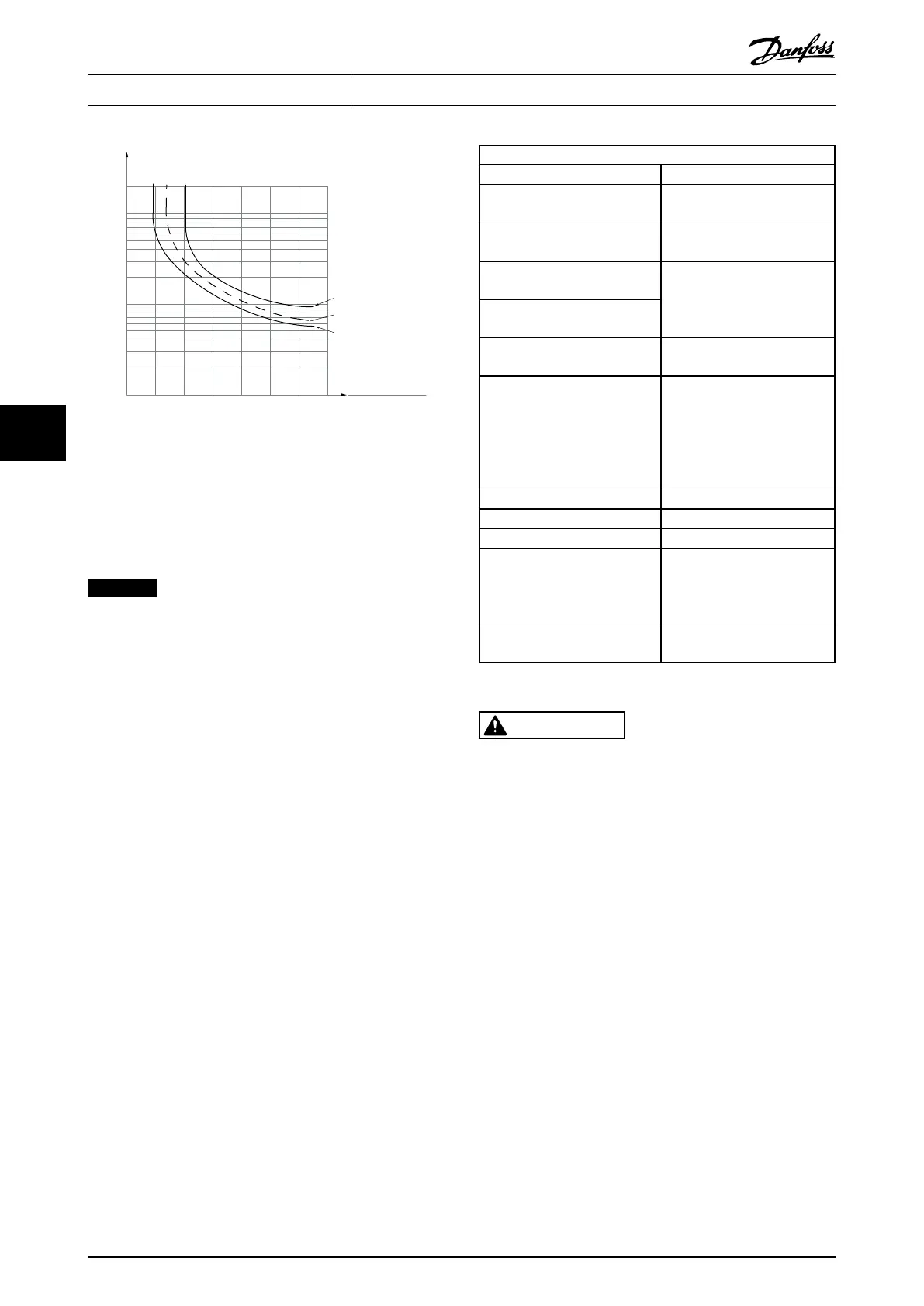
t [s]
175ZA052.12
f
OUT
= 2 x f
M,N
f
OUT
= 0.2 x f
M,N
f
OUT
= 1 x f
M,N
(par. 1-23)
I
MN
(par. 1-24)
I
M
Illustration 6.5 ETR profile
ATEX ETR
The B-option PTC Thermistor Card MCB 112 offers ATEX
approved monitoring of motor temperature. Alternatively,
an external ATEX approved PTC protection device can be
used.
NOTICE
Use only ATEX Ex-e approved motors for this function.
See motor nameplate, approval certificate, data sheet or
contact the motor supplier.
When controlling an Ex-e motor with “Increased Safety,” it
is important to ensure certain limitations. The parameters
that must be programmed are presented in the following
application example.
Parameters
Function Setting
parameter 1-90 Motor Thermal
Protection
[20] ATEX ETR
1-94 ATEX ETR cur.lim. speed
reduction
20%
1-98 ATEX ETR interpol. points
freq.
Motor name plate
1-99 ATEX ETR interpol points
current
Parameter 1-23 Motor
Frequency
Enter the same value as for
4-19 Max Output Frequency
4-19 Max Output Frequency Motor name plate, possibly
reduced for:
•
long motor cables
•
sinus filter
•
reduced supply voltage
4-18 Current Limit Forced to 150% by 1–90 [20]
5-15 Terminal 33 Digital Input
[80] PTC Card 1
5-19 Terminal 37 Safe Stop
[4] PTC 1 Alarm
14-01 Switching Frequency Check that the default value
fulfils the requirement from
the motor name plate. If not,
use a sine wave filter.
14-26 Trip Delay at Inverter
Fault
0
Table 6.3 ATEX Ex-e Programming Example
CAUTION
It is mandatory to compare the minimum switching
frequency requirement stated by the motor
manufacturer to the minimum switching frequency of
the frequency converter in 14-01 Switching Frequency. If
the frequency converter does not meet this requirement,
use a sine wave filter.
Klixon
The Klixon type thermal circuit breaker uses a
®
metal dish.
At a predetermined overload, the heat caused by the
current through the disc causes a trip.
Using a digital input and 24 V as power supply:
Example: The frequency converter trips when the motor
temperature is too high
Parameter set-up:
Set parameter 1-90 Motor Thermal Protection to [2]
Thermistor Trip
Set parameter 1-93 Thermistor Source to [6] Digital Input
Programming
Operating Instructions
54 Danfoss A/S © Rev. 2014-07-29 All rights reserved. MG37A202
66

 Loading...


