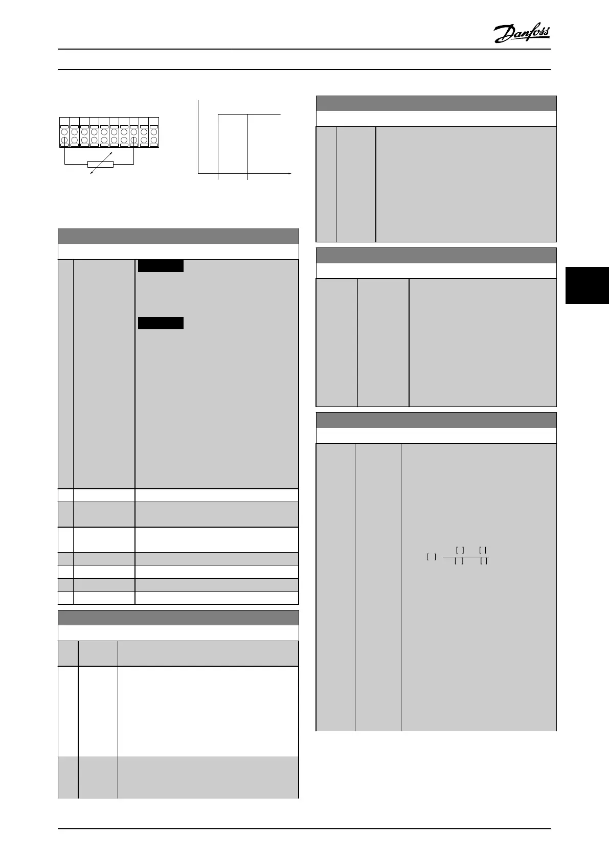
PTC / Thermistor
OFF
ON
+24V
12 13 18 3732
A
2719 29 33
B
20
GND
R<6.6 k Ω >10.8 k Ω
130BA151.11
Illustration 6.6 Klixon Example
1-93 Thermistor Source
Option: Function:
NOTICE
This parameter cannot be adjusted
while the motor is running.
NOTICE
Set digital input to [0] PNP - Active at
24 V in 5-00 Digital I/O Mode.
Select the input to which the thermistor
(PTC sensor) should be connected. An
analog input option [1] or [2] cannot be
selected if the analog input is already in use
as a reference source (selected in
3-15 Reference 1 Source, 3-16 Reference 2
Source or 3-17 Reference 3 Source).
When using MCB 112, option [0] None must
always be selected.
[0] None
[1] Analog Input
53
[2] Analog Input
54
[3] Digital input 18
[4] Digital input 19
[5] Digital input 32
[6] Digital input 33
2-10 Brake Function
Option: Function:
[0]
*
Off No brake resistor is installed.
[1] Resistor
brake
A brake resistor is incorporated in the system, for
dissipation of surplus brake energy as heat.
Connecting a brake resistor allows a higher DC
link voltage during braking (generating
operation). The Resistor brake function is only
active in frequency converters with an integral
dynamic brake.
[2] AC brake Is selected to improve braking without using a
brake resistor. This parameter controls an
overmagnetisation of the motor when running
2-10 Brake Function
Option: Function:
with a generatoric load. This function can
improve the OVC-function. Increasing the
electrical losses in the motor allows the OVC
function to increase the braking torque without
exceeding the overvoltage limit. Note that AC
brake is not as effective as dynamic braking with
a resistor.
AC brake is for VVC
plus
and flux mode in both
open and closed loop.
2-11 Brake Resistor (ohm)
Range: Function:
Size
related*
[ 5.00 -
65535.00
Ohm]
Set the brake resistor value in Ω. This
value is used for monitoring the power
to the brake resistor in 2-13 Brake
Power Monitoring. This parameter is
only active in frequency converters
with an integral dynamic brake.
Use this parameter for values without
decimals. For a selection with 2
decimals, use 30-81 Brake Resistor
(ohm).
2-12 Brake Power Limit (kW)
Range: Function:
Size
related*
[ 0.001 -
2000.000
kW]
Parameter 2-12 Brake Power Limit (kW) The
expected average power dissipated in the
brake resistor over a period of 120 s. It is
used as the monitoring limit for
16-33 Brake Energy /2 min and specifies
when a warning/alarm is issued.
To calculate 2–12 Brake Power Limit (kW),
use the following formula:
P
br,avg
W
=
U
br
2
V
×
t
br
s
R
br
Ω
×
T
br
s
P
br,avg
is the average power dissipated in
the brake resistor
R
br
is the resistance of the brake resistor.
t
br
is the active breaking time within the
120 s period, T
br
.
U
br
is the DC voltage where the brake
resistor is active, depending on the unit
as follows:
T2 units: 390 V
T4 units: 778 V
T5 units: 810 V
T6 units: 943V/1099V for D – F frames
T7 units: 1,099 V
Programming Operating Instructions
MG37A202 Danfoss A/S © Rev. 2014-07-29 All rights reserved. 55
6 6

 Loading...


