EasyManuals Logo

Danfoss VLT series Service Manual

Danfoss VLT series
158 pages
To Next Page IconTo Next Page
To Previous Page IconTo Previous Page
Page #101 background imageLoading...
Page #101 background image
6-5
VLT is a registered Danfoss trademark
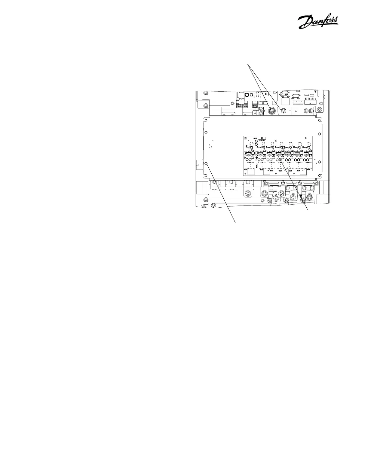
6.7.3 Single Capacitor Bank D1 Units
1. Remove control card cassette in accordance with
instructions.
2. Remove 2 capacitor bank retaining nuts (10mm)
from DC bus bars. A minimum 4 in. (100mm)
extension is required.
3. Disconnect MK102, MK103, MK104, and MK106
from gate drive card. Also remove MK105, for
units with extended brake, and MK101 for units
with RFI filter. Note that IGBT gate drive card can
remain attached to cap bank cover plate.
4. Remove 4 retaining nuts (10mm) from cap bank
cover plate and remove plate.
5. Note that weight of cap bank is approx. 20 lbs. (9
kg). Remove cap bank by pulling free from
mounting studs.
Reinstall in reverse order of this procedure. Tighten mounting
screws to 35 in-lbs (4 Nm).
Figure 6-6. D1 Single Capacitor Bank Assembly
Retaining nuts
(Step 2)
Gate drive card
(Step 3)
Retaining nuts
(Step 4)

Table of Contents

Other manuals for Danfoss VLT series

Questions and Answers:

Question and Answer IconNeed help?

Do you have a question about the Danfoss VLT series and is the answer not in the manual?

Danfoss VLT series Specifications

General IconGeneral
SeriesVLT
CategoryDC Drives
Output Voltage0-100% of input voltage
Protection FeaturesOvervoltage, Undervoltage, Overcurrent, Overtemperature, Short Circuit, Ground Fault
Communication InterfacesProfibus, CANopen
Enclosure RatingIP20, IP21, IP55, IP66
Cooling MethodForced Air Cooling, Convection Cooling
Control ModeSensorless Vector, Closed Loop Vector
Ambient Temperature-10°C to +50°C (14°F to 122°F)

Related product manuals