2-10
VLT is a registered Danfoss trademark
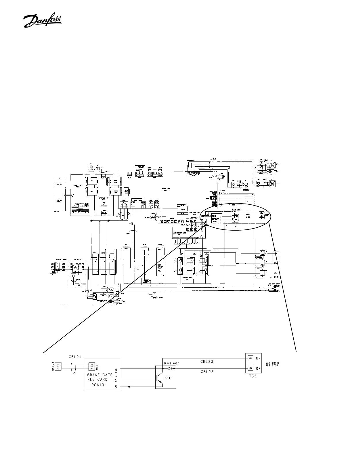
Brake Option
For drives equipped with the dynamic brake option, a brake
IGBT along with terminals 81(R-) and 82(R+) is included for
connecting an external brake resistor.
The function of the brake IGBT (see Figure 2-8) is to limit the
voltage in the intermediate circuit, whenever the maximum
voltage limit is exceeded. It does this by switching the externally
mounted resistor across the DC bus to remove excess DC
voltage present on the bus capacitors. Excess DC bus voltage
is generally a result of an overhauling load causing regenerative
energy to be returned to the DC bus. This occurs, for example,
when the load drives the motor causing the voltage to return
to the DC bus circuit.
Figure 2-8. Brake Option
Placing the brake resistor externally has the advantages of
selecting the resistor based on application need, dissipating
the energy outside of the control panel, and protecting the
drive from overheating if the brake resistor is overloaded.
The Brake IGBT gate signal originates on the control card
and is delivered to the brake IGBT via the power card and
gate drive card. Additionally, the power and control cards
monitor the brake IGBT and brake resistor connection for
short circuits and overloads.

 Loading...


