EasyManuals Logo

Danfoss VLT series Service Manual

Danfoss VLT series
158 pages
To Next Page IconTo Next Page
To Previous Page IconTo Previous Page
Page #104 background imageLoading...
Page #104 background image
6-8
VLT is a registered Danfoss trademark
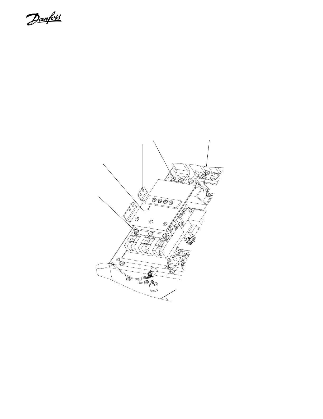
4. Remove six retaining screws (T25) from SCR/
Diode modules, terminals 2 and 3 in each module.
5. Remove four (10mm) retaining nuts from DC
inductor input bus bars and four retaining nuts (not
shown) from side mounted bus bars. (Side
mounted bus bars are only present on units with
load sharing.) Remove DC input bus assembly.
CONTINUED ON NEXT PAGE
Retaining screws
(Step 4)
Retaining nuts
(Step 5)
DC input bus assembly BB3
(Step 5)
Soft Charge Resistor
Figure 6-8. D1 Soft Charge Resistor (2 of 3)

Table of Contents

Other manuals for Danfoss VLT series

Questions and Answers:

Question and Answer IconNeed help?

Do you have a question about the Danfoss VLT series and is the answer not in the manual?

Danfoss VLT series Specifications

General IconGeneral
SeriesVLT
CategoryDC Drives
Output Voltage0-100% of input voltage
Protection FeaturesOvervoltage, Undervoltage, Overcurrent, Overtemperature, Short Circuit, Ground Fault
Communication InterfacesProfibus, CANopen
Enclosure RatingIP20, IP21, IP55, IP66
Cooling MethodForced Air Cooling, Convection Cooling
Control ModeSensorless Vector, Closed Loop Vector
Ambient Temperature-10°C to +50°C (14°F to 122°F)

Related product manuals