5-12
VLT is a registered Danfoss trademark
5.1.10 Fan Continuity Tests: E-frame Sizes
Make all continuity checks using an ohmmeter set to Rx1
scale. A digital or analog ohmmeter can be used. Some
instability may result when measuring resistance of a
transformer with a multimeter. This can be reduced by turning
off the auto-ranging function and setting the measurement
manually.
To aid in making the measurements, unplug MK107 from the
power card.
5.1.10.1 Checking Continuity of Connections
For the following tests, read connector MK107 on the power
card.
1. Measure from L3 (T) to MK107 terminal 8.
Reading of <1ohm should be indicated.
2. Measure from L2 (S) to MK107 terminal 1.
Reading of <1 ohm should be indicated.
Incorrect Reading
An incorrect reading would indicate a faulty cable connection.
Replace the cable assembly.
Fan Fuse Test
1. Test fan fuses on power card mounting plate by
checking continuity across fuse.
An open fuse could indicate additional faults. Replace fuse
and continue fan checks.
5.1.10.2 Ohm Test of Transformer
For the following tests, read the plug end of the wire connected
to MK107 on the power card.
1. Measure between MK107 terminals 1 and 8.
Should read approx value A in Table 5-1.
2. Measure between MK107 terminals 8 and 12.
Should read approx value B in Table 5-1.
3. Measure between MK107 terminals 1 and 12.
Should read approx value C in Table 5-1.
Table 5-1. Fan Transformer Resistance
5.1.10.3 Ohm Test of Fans
1. Measure between terminals 3 and 5 of power
card connector MK107. Should read approx
value D in Table 5-1.
Incorrect Reading
For fans without an inductor, replace the fan. For drives with a
fan and inductor, isolate the fault between the fan and the
inductor as follows.
a. Disconnect CN3 and measure resistance
between pins 1 and 2 on fan side of conector.
Reading should be approx 4 ohms. If
incorrect, replace fan.
b. Disconnect CN4 and CN5. Measure
resistance across inductor. Reading should be
less than 1 ohm. If incorrect, replace inductor.
2. Measure between terminals 11 and 13 of power
card connector MK107. For units with one top
mounted fan, a reading of 400 ohms is
expected. For units with two door mounted
fans, a reading of 200 ohms is expected.
Incorrect Reading
For units with one top mounted fan, replace the fan. For units
with two door mounted fans, isolate the faulty fan as follows.
a. Disconnect wiring from fan terminals.
b. Read across fan terminals on each fan. A
reading of 400 ohms is expected. Replace
any defective fans.
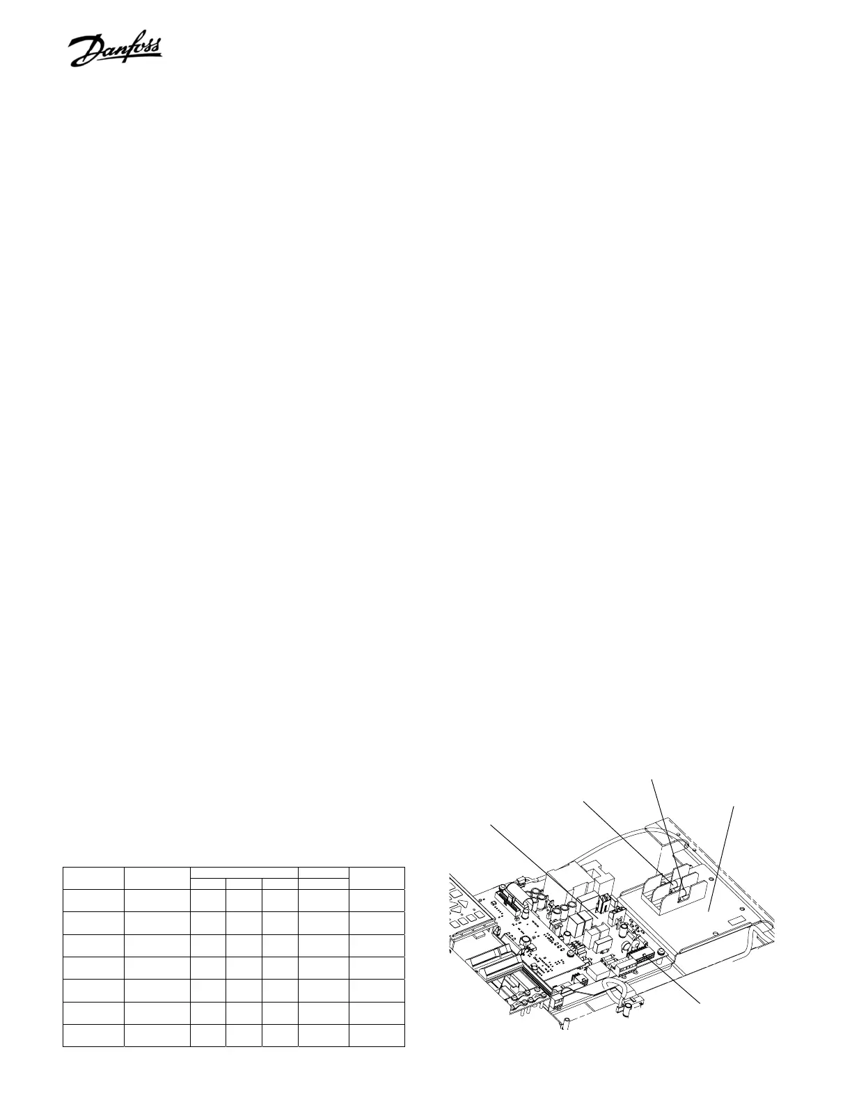
Figure 5-7. Fan and DC Bus Fuse Locations
Power card
Mounting plate
Fan fuse
DC bus fuse
MK107
Incorrect Reading
An incorrect reading would indicate a defective fan transformer.
Replace the fan transformer.
When finished reconnect MK107.
Resistance (in Ohms)
Heatsink Fan
AC Voltage Drive
A B C D
Fan
Inductor
380-500 5352, 4452,
6402, 8452
15 12 4 21 no
380-500 5452, 4502,
6502, 8502
4 3 1 4 yes
380-500 5502, 4602,
6552, 8602
4 3 1 4 yes
380-500 5552, 4652,
6602, 8652
4 3 1 4 yes
525-690 5402, 4502,
6502, 8502
20 8 12 21 no
525-690 5502, 4602,
6602, 8602
7.4 3.6 3.2 4 yes
525-690 5602, 4652,
6652, 8652
7.4 3.6 3.2 4 yes

 Loading...


