7-1
VLT is a registered Danfoss trademark
7.0 INSTRUCTIONS
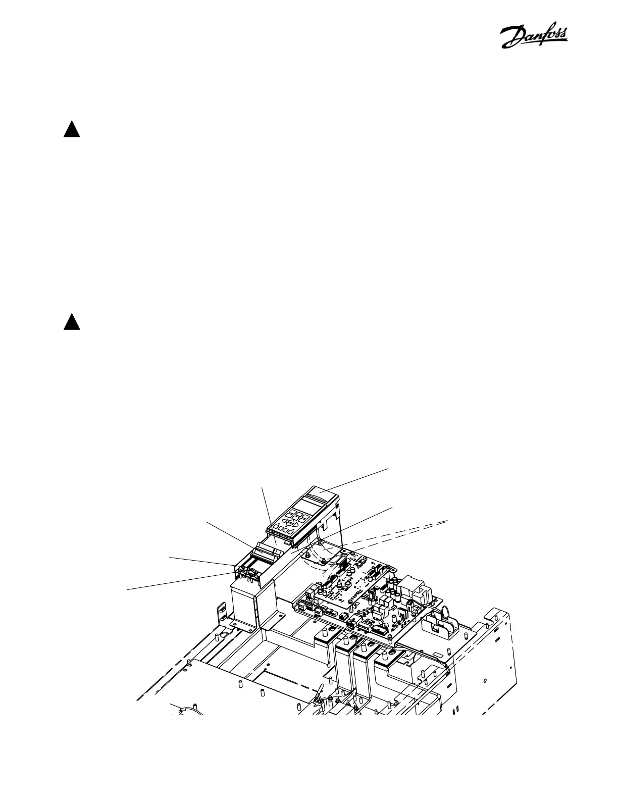
7.1 Control Card Cassette
1. Remove control wiring by unplugging control
terminals.
2. Remove grounding clamps by removing two
screws holding each in place. Save screws for
reassembly.
3. Disconnect cable between LCP and control card.
4. Unplug two ribbon cables from side of control
card.
5. Loosen two captive screws to free cassette (T20).
6. Slide cassette free from mounting tabs.
7. Remove and replace control card in accordance
with instructions included with replacement card.
Reinstall in reverse order of this procedure. Ensure that two
ribbon cables are not crossed. Tighten control card mounting
screws to 10 in-lbs (1 Nm).
SECTION 7
E-FRAME SIZES DISASSEMBLY AND ASSEMBLY INSTRUCTIONS
DANGER
!
Drives contain dangerous voltages when
connected to line voltage. No disassembly
should be attempted with power applied. Remove
power to drive and wait at least 40 minutes to let
drive capacitors fully discharge. Only a
competent technician should carry out service.
ELECTROSTATIC DISCHARGE (ESD)
Many electronic components within the adjustable frequency
drive are sensitive to static electricity. Voltages so low that
they cannot be felt, seen or heard can reduce the life, affect
performance, or completely destroy sensitive electronic
components.
CAUTION
!
Use proper electrostatic discharge (ESD)
procedures when servicing drive to prevent
damage to sensitive components.
NOTE
Frame size is used throughout this manual where
ever procedures or components differ between
drives based upon the unit's physical size. Refer
to tables in the Introduction Section to determine
E1 frame size definitions.
Figure 7-1. Control Card Cassette
Control card cassette
Control terminals
(Step 1)
Captive screws
(Step 5)
Ribbon cables
(Step 4)
Control card
Grounding clamps
(Step 2)
LCP (local control panel)

 Loading...


