6-26
VLT is a registered Danfoss trademark
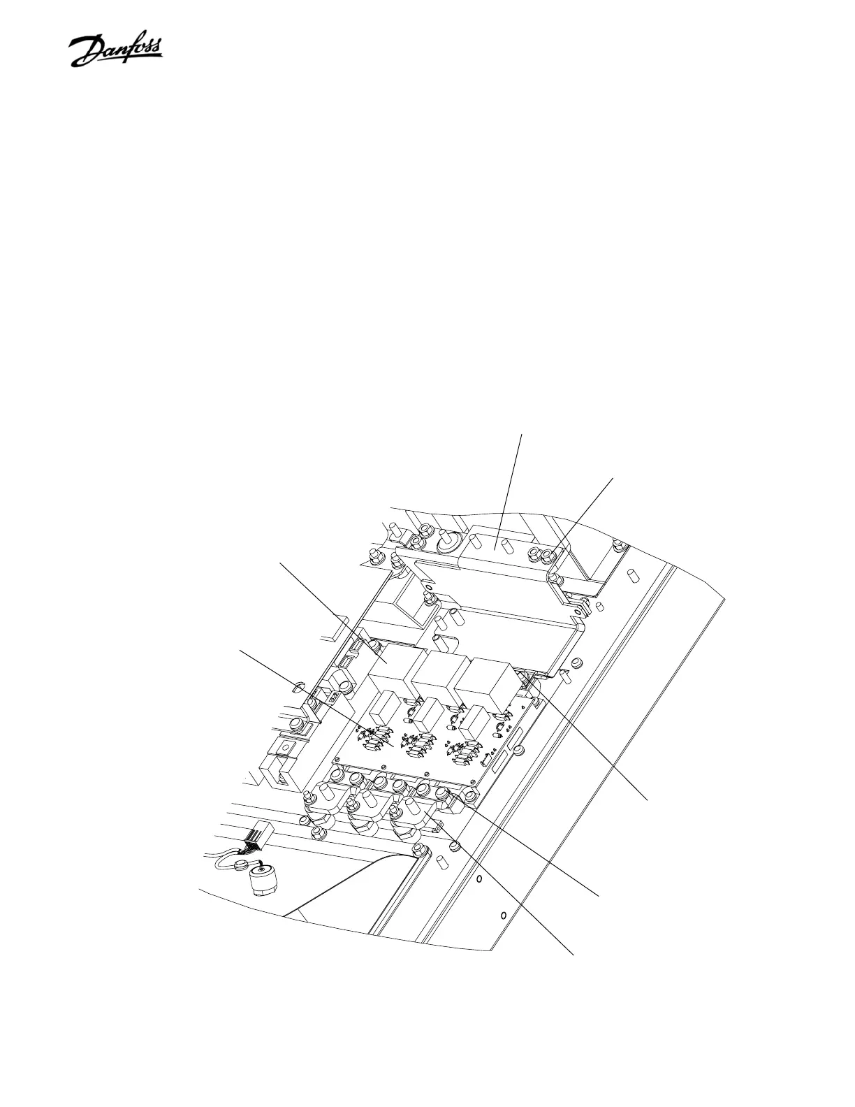
Retaining nut
(Step 8)
IGBT bus bar assembly
(Step 8)
Snubber capacitor
(Step 9)
Retaining screw
(Step 9)
IGBT module
Retaining nut
(Step 11)
Intermediate IGBT output bus bar
(Step 11)
REASSEMBLY
1. Replace IGBT module in accordance with
instrucions enclosed with replacement module.
2. Tighten remaining T25 and 8mm screws to 20 in-
lbs (2.25 Nm) and T30 and 10 mm to 35 in-lbs (4
Nm).
3. Reassemble drive in reverse order of disassembly
and tighten attaching hardware in accordance
with torque tables.
8. Remove 4 (10mm) retaining nuts at top of IGBT
bus bar assy.
9. Remove 6 retaining screws on upper portion of
IGBT modules. These screws also attach the
snubber capacitors to the IGBT modules.
Remove 3 snubber capacitors.
10. Remove IGBT bus bar assy.
11. At bottom end of IGBT module, remove 6
retaining screws (2 each for U, V, and W
intermediate IGBT output bus bars).
12. Remove retaining nut (8mm) from 3 intermediate
IGBT output bus bars. Remove intermediate IGBT
output bus bars.
13. Remove IGBT module.
14. Clean heatsink surface with mild solvent or alcohol
solution.
Figure 6-16. D1 IGBT Module (2 of 2)

 Loading...


