5-11
VLT is a registered Danfoss trademark
5.1.9 Fan Continuity Tests: D-frame Size
Make all continuity checks using an ohmmeter set to Rx1
scale. Digital or analog ohmmeter can be used.
To aid in making the measurements, unplug the connector
CN2 from its mate. CN2 terminals correspond to the terminal
numbers labeled on the transformer.
5.1.9.1 Checking Continuity of Connections
For the following tests, read the plug end of connector CN2
that is not connected to the transformer.
1. Measure from L3 (T) to CN2 terminal 1. A
reading of <1ohm should be indicated.
2. Measure from L2 (S) to CN2 terminal 3. A
reading of <1 ohm should be indicated.
3. Measure from CN2 terminal 2 to terminal 12 of
power card connector MK107. A reading of <1
ohm should be indicated.
Incorrect Reading
An incorrect reading would indicate a faulty cable connection.
Replace the cable assembly.
5.1.9.2.1 Ohm Test of Transformer (380 - 500V)
For the following tests, read the plug end of connector CN2
that is connected to the transformer.
1. Measure between CN2 terminals 1 and 3.
Approximately 15 ohms should be read.
2. Measure between CN2 terminals 1 and 2.
Approximately 12 ohms should be read.
3. Measure between CN2 terminals 2 and 3.
Approximately 4 ohms should be read.
Incorrect Reading
An incorrect reading would indicate a defective fan transformer.
Replace the fan transformer.
When finished, be sure to reconnect CN2.
5.1.9.2.2 Ohm Test of Transformer (525 - 690V)
For the following tests, read the plug end of connector CN2
that is connected to the transformer.
1. Measure between CN2 terminals 1 and 3.
Approximately 20 ohms should be read.
2. Measure between CN2 terminals 1 and 2.
Approximately 8 ohms should be read.
3. Measure between CN2 terminals 2 and 3.
Approximately 12 ohms should be read.
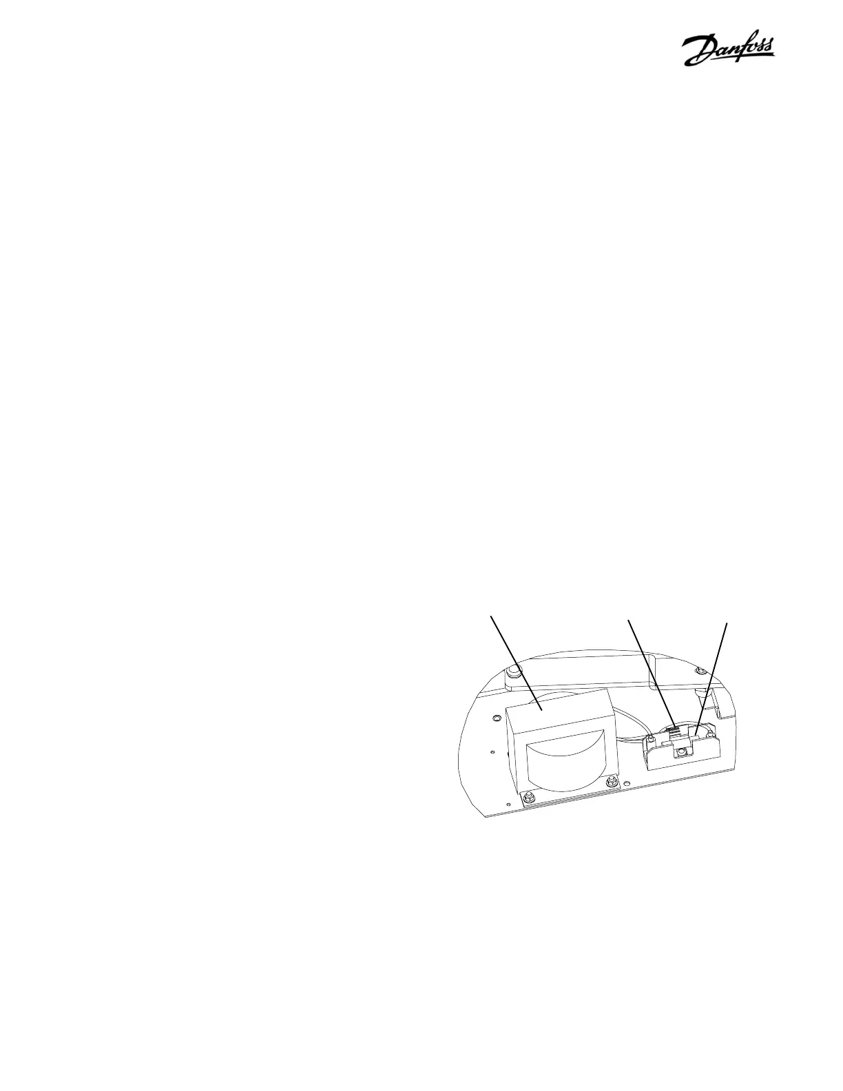
Figure 5-6. Fan Transformer and Fuse Location
Incorrect Reading
An incorrect reading would indicate a defective fan transformer.
Replace the fan transformer.
When finished, be sure to reconnect CN2.
5.1.9.3 Ohm Test of Fans
1. Measure between terminals 11 and 13 of power
card connector MK107. A reading of 20 ohms
should be indicated.
2. Disconnect spade connectors from door fan and
repeat measurement. A reading of 21 ohms
should be indicated.
3. Read terminals of door fan with wires
disconnected. A reading of 400 ohms should be
indicated.
4. Reconnect wires to door fan.
Incorrect Reading
An incorrect reading of one or both of the fans indicates a
defective fan. Replace the defective fan.
Fan transformer
Fan fuseCN2

 Loading...


