7-11
VLT is a registered Danfoss trademark
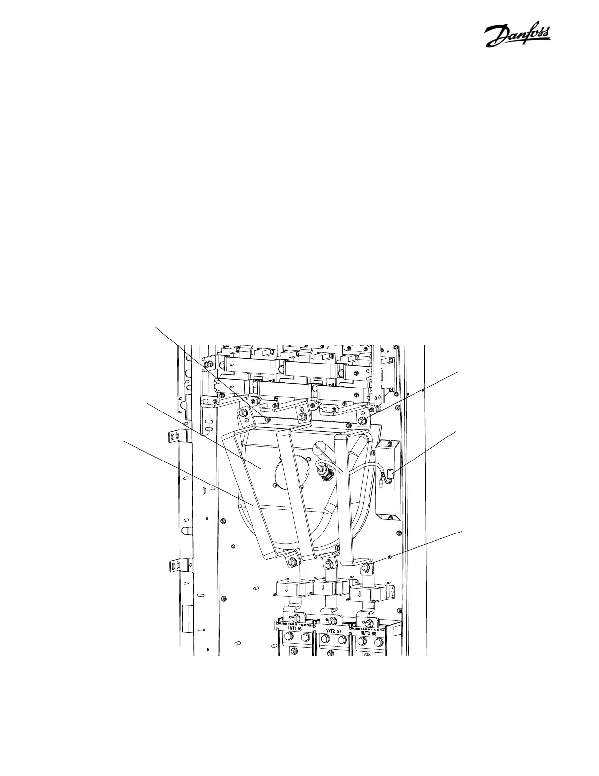
IGBT output bus bar
BB49
Retaining nut
(Step 3)
Retaining nut
(Step 2)
Molex connector
(Step 4)
Fan housing
Figure 7-10. Fan Assembly
7.12 Fan Assembly
1. Remove input terminal plate in accordance with
procedure.
2. Remove retaining nut (17 mm) or T50 Torx screw,
depending on unit type, connecting each of 3 IGBT
over-fan bus bars to 3 current sensor bus bars.
3. Remove retaining nut (17 mm) connecting each of
three IGBT over-fan bus bars to three IGBT
output bus bars.
4. Disconnect in-line Molex connector in fan wiring.
Cut tie wrap to free wiring from frame.
Retaining nut
(Step 5)
5. Remove fan assembly by removing 6 retaining
nuts (10 mm). Note that fan assembly weights
approximately 25 pounds (11 kg).
Reinstall in reverse order of this procedure. Tighten 10 mm
retaining nuts to 35 in-lbs (4.0 Nm) and 17 mm connecting
nuts or T50 screw to 170 in-lbs (19.2 Nm).

 Loading...


