EasyManuals Logo

Danfoss VLT series Service Manual

Danfoss VLT series
158 pages
To Next Page IconTo Next Page
To Previous Page IconTo Previous Page
Page #111 background imageLoading...
Page #111 background image
6-15
VLT is a registered Danfoss trademark
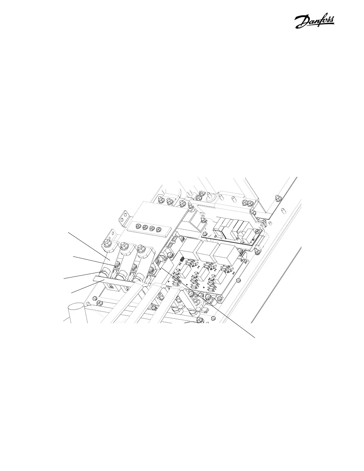
6.12 SCR/Diode Module D1 Units
1. Remove capacitor bank per instruction.
2. Remove input terminal mounting plate per
instructions.
3. Remove retaining screw (T25) from terminal 1 of
each SCR/Diode module.
4. Remove 8mm retaining nut from bus bar holding
bracket and remove bus bar.
CONTINUED ON NEXT PAGE
Retaining screw access
(Step 3)
Bus bar BB2
(Step 4)
Figure 6-11. D1 SCR/Diode Module (1 of 3)
SCR/Diode module
Retaining nut
(Step 4)
Bus bar BB1

Table of Contents

Other manuals for Danfoss VLT series

Questions and Answers:

Question and Answer IconNeed help?

Do you have a question about the Danfoss VLT series and is the answer not in the manual?

Danfoss VLT series Specifications

General IconGeneral
SeriesVLT
CategoryDC Drives
Output Voltage0-100% of input voltage
Protection FeaturesOvervoltage, Undervoltage, Overcurrent, Overtemperature, Short Circuit, Ground Fault
Communication InterfacesProfibus, CANopen
Enclosure RatingIP20, IP21, IP55, IP66
Cooling MethodForced Air Cooling, Convection Cooling
Control ModeSensorless Vector, Closed Loop Vector
Ambient Temperature-10°C to +50°C (14°F to 122°F)

Related product manuals