EasyManuals Logo

Danfoss VLT series Service Manual

Danfoss VLT series
158 pages
To Next Page IconTo Next Page
To Previous Page IconTo Previous Page
Page #132 background imageLoading...
Page #132 background image
7-10
VLT is a registered Danfoss trademark
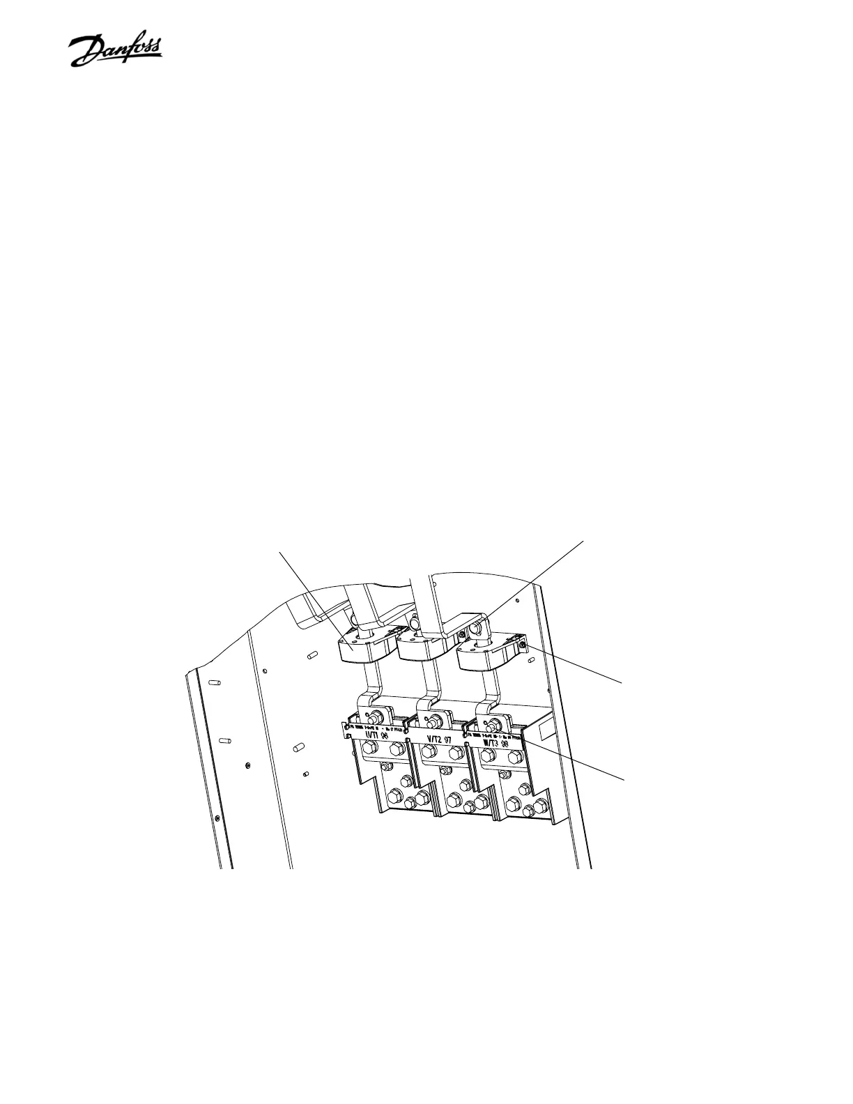
7.11 Current Sensor
1. Remove input terminal plate in accordance with
procedure.
2. Remove retaining nut (17 mm) connecting current
sensor bus bar to motor terminal bus bar.
3. Remove retaining nut (17 mm) or T50 screw,
depending on unit type, connecting current
sensor bus bar to IGBT over fan bus bar.
4. Note which cable is attached to current sensor.
Ensure that correct cable is attached upon
reassembly. Unplug cable from current sensor
being removed.
5. Remove the 2 retaining nuts (size varies with
model) from stud on baseplate and remove
sensor.
Reinstall in reverse order of this procedure. Tighten 17 mm
retaining nuts or T50 screw to 170 in-lbs (19.2 Nm).
Figure 7-9. Current Sensors
Current sensor
Output motor terminal
bus bar retaining nut
(Step 2)
IGBT terminal bus bar
mounting screw
(Step 3)
Current sensor
mounting screws (2)
(Step 5)

Table of Contents

Other manuals for Danfoss VLT series

Questions and Answers:

Question and Answer IconNeed help?

Do you have a question about the Danfoss VLT series and is the answer not in the manual?

Danfoss VLT series Specifications

General IconGeneral
SeriesVLT
CategoryDC Drives
Output Voltage0-100% of input voltage
Protection FeaturesOvervoltage, Undervoltage, Overcurrent, Overtemperature, Short Circuit, Ground Fault
Communication InterfacesProfibus, CANopen
Enclosure RatingIP20, IP21, IP55, IP66
Cooling MethodForced Air Cooling, Convection Cooling
Control ModeSensorless Vector, Closed Loop Vector
Ambient Temperature-10°C to +50°C (14°F to 122°F)

Related product manuals