EasyManuals Logo

Danfoss VLT series Service Manual

Danfoss VLT series
158 pages
To Next Page IconTo Next Page
To Previous Page IconTo Previous Page
Page #115 background imageLoading...
Page #115 background image
6-19
VLT is a registered Danfoss trademark
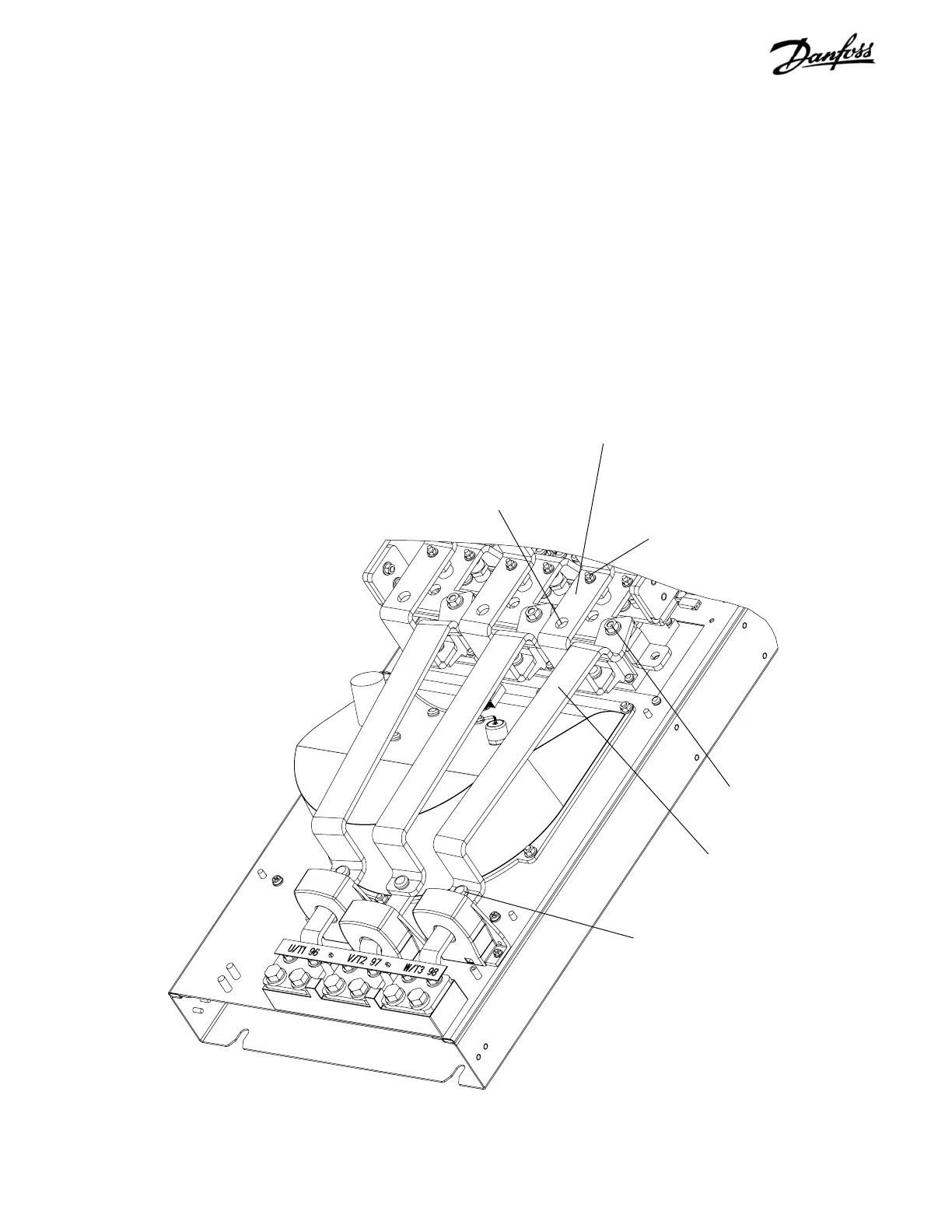
IGBT output bus bar
(Step 2)
Retaining nut
(Step 2)
Retaining nut
(Step 2)
Retaining nut
(Step 4)
Intermediate SCR input bus bar
(Step 3)
Terminal
(Step 3)
Figure 6-13. Fan Assembly (1 of 2)
6.14 Fan Assembly
1. Remove input terminal mounting plate assembly
per instructions.
2. Remove 3 IGBT output bus bars by removing 6
retaining nuts (8mm), one from each end, of IGBT
output bus bars. Remove bus bars.
NOTE
Omit steps 3 and 4 for D2 units.
3. Use 4 in. (100mm) minimum extension and
remove terminal 1 of SCR/Diode module.
4. Note the color coding for each of three wires
attached to retaining studs. Ensure that correct
wire is attached to applicable stud upon
reassembling. Remove AC power lead to
intermediate SCR input bus bar by removing nut
(8mm) and remove bus bar.
CONTINUED ON NEXT PAGE

Table of Contents

Other manuals for Danfoss VLT series

Questions and Answers:

Question and Answer IconNeed help?

Do you have a question about the Danfoss VLT series and is the answer not in the manual?

Danfoss VLT series Specifications

General IconGeneral
SeriesVLT
CategoryDC Drives
Output Voltage0-100% of input voltage
Protection FeaturesOvervoltage, Undervoltage, Overcurrent, Overtemperature, Short Circuit, Ground Fault
Communication InterfacesProfibus, CANopen
Enclosure RatingIP20, IP21, IP55, IP66
Cooling MethodForced Air Cooling, Convection Cooling
Control ModeSensorless Vector, Closed Loop Vector
Ambient Temperature-10°C to +50°C (14°F to 122°F)

Related product manuals