7-12
VLT is a registered Danfoss trademark
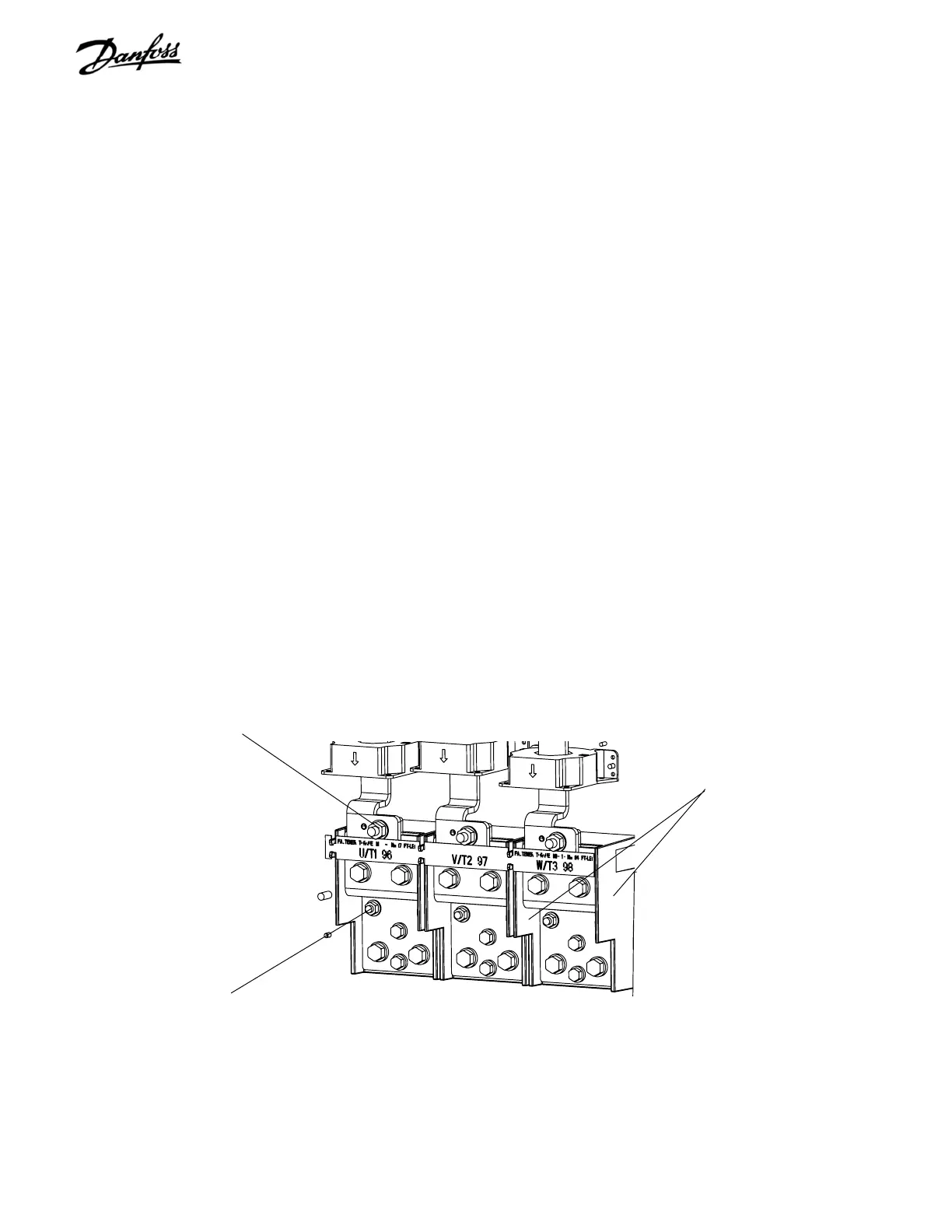
7.13 AC Input, Motor, Load Sharing or Regen
Terminals
1. Remove external wiring from terminals as
required.
2. Remove retaining nut (17 mm) connecting
terminal bus bar to other bus bar assemblies.
3. Remove 2 retaining nuts (13 mm) attaching
terminal bus bar to terminal block insulation. Slide
terminal bus bar out.
4. If terminal block is attached to input terminal plate
(not shown), remove retaining screw (T40)
attaching terminal block insulation, otherwise go
to step 5.
5. If terminal block is not attached to the input
terminal plate, remove retaining nut (13 mm)
attaching terminal block insulation.
Reinstall in reverse order of this procedure. Tighten 17 mm
connecting nuts to 170 in-lbs (19.2 Nm) and 13 mm or T40
Torx screw to 85 in-lbs (9.6 Nm).
Figure 7-11. Terminal Blocks
Terminal block insullation
(Step 4 or 5)
Retaining nuts
(Step 3)
Retaining nut
(Step 2)

 Loading...


