EasyManuals Logo

Danfoss VLT series Service Manual

Danfoss VLT series
158 pages
To Next Page IconTo Next Page
To Previous Page IconTo Previous Page
Page #117 background imageLoading...
Page #117 background image
6-21
VLT is a registered Danfoss trademark
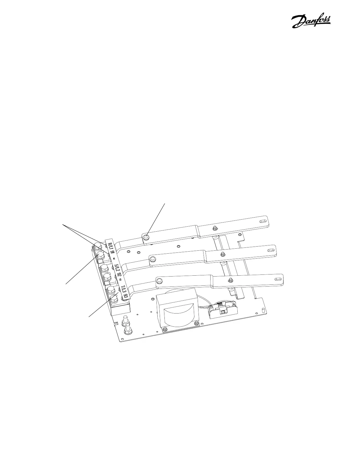
6.15 AC Input Terminals
1. Remove AC input power cabling, as required.
2. Remove R/L1, S/L2, T/L3 terminals by removing 3
retaining screws.
Reinstall in reverse order of this procedure. Tighten mounting
nuts per specifications in the unit's instruction manual.
Figure 6-14. AC Input Terminals
AC input terminal
AC input cable connector
(Step 1)
Retaining screws
(Step 2)
Retaining screw
(Step 2)

Table of Contents

Other manuals for Danfoss VLT series

Questions and Answers:

Question and Answer IconNeed help?

Do you have a question about the Danfoss VLT series and is the answer not in the manual?

Danfoss VLT series Specifications

General IconGeneral
SeriesVLT
CategoryDC Drives
Output Voltage0-100% of input voltage
Protection FeaturesOvervoltage, Undervoltage, Overcurrent, Overtemperature, Short Circuit, Ground Fault
Communication InterfacesProfibus, CANopen
Enclosure RatingIP20, IP21, IP55, IP66
Cooling MethodForced Air Cooling, Convection Cooling
Control ModeSensorless Vector, Closed Loop Vector
Ambient Temperature-10°C to +50°C (14°F to 122°F)

Related product manuals