6-2
VLT is a registered Danfoss trademark
6.2 Interface Card
1. Disconnect cables from connectors on interface
card MK100, MK102 and MK105. Disconnect
cables from connectors MK101 and MK103 only if
replacing interface card.
2. Remove interface card by remove 4 mounting
screws (T25 Torx) from standoffs.
Reinstall in reverse order of this procedure. Tighten T25
screws and interface card standoffs to 20 in-lbs (2.25 Nm).
Card will initialize in service mode. Follow instructions to enter
data required.
6.3 Power Card
1. Remove interface card in accordance with
procedure.
2. Disconnect cables from connectors on power
card MK100, MK102, MK104, MK105, MK106,
MK107, MK109, MK110, and FK100.
3. Remove 2 interface card standoffs (8mm).
4. Remove power card by removing 5 mounting
screws (T25 Torx) from standoffs.
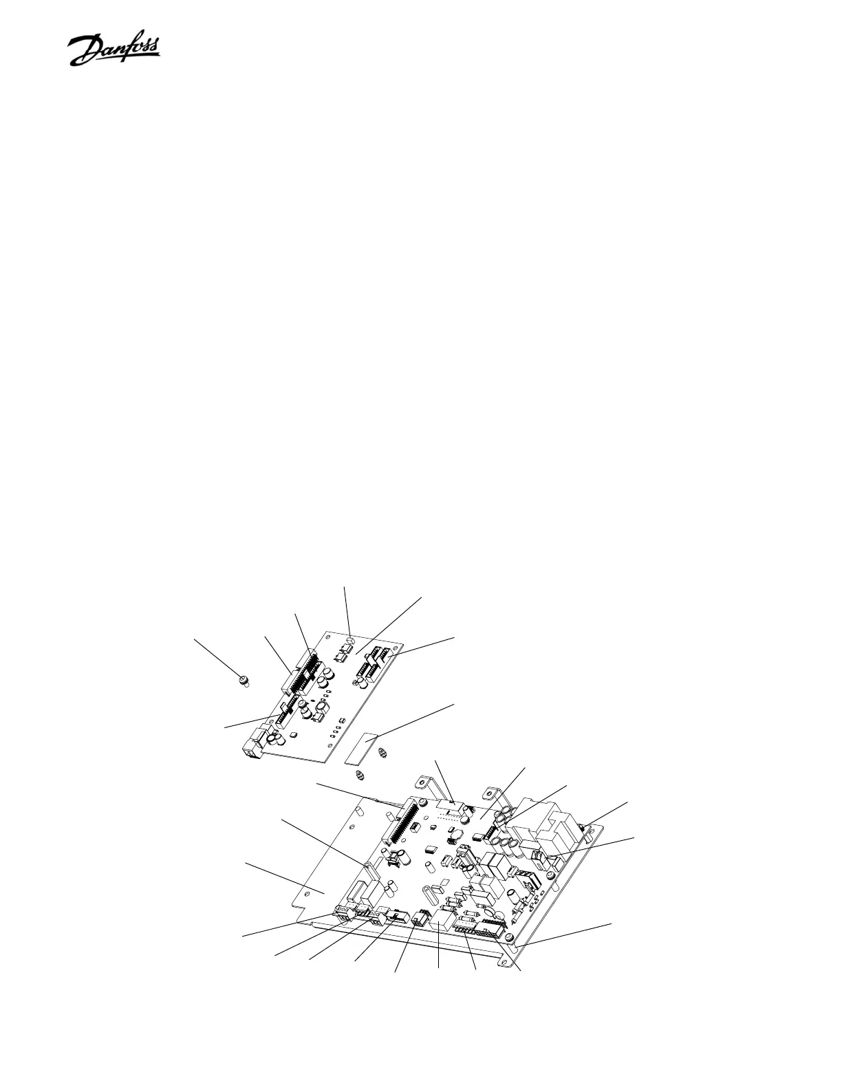
Figure 6-2. Interface Card, Power Card, and Mounting Plate
Interface card
PCA2
Interface card
mounting screw
Power card
PCA3
5. Remove current scaling card from power card by
pushing in retaining clips on standoffs. KEEP THIS
SCALING CARD TO REINSTALL ON ANY
REPLACEMENT POWER CARD. Scaling card
controls signals operating with this specific VLT
drive. Scaling card is not part of replacement
power card.
Reinstall in reverse order of this procedure. Tighten mounting
screws and interface card standoffs to 20 in-lbs (2.25 Nm).
6.4 Control Card/Power Card Mounting Plate
1. Remove control card cassette and interface card
in accordance with procedures.
2. Remove 4 mounting nuts (10mm).
3. Disconnect all cabling from power card.
4. Remove optional wiring connections, as
necessary, to free mounting plate.
5. Lift plate free from chassis.
Reinstall in reverse order of this procedure. Torque T25
mounting screws to 20 in-lbs (2.25 Nm).
Mounting plate
Interface card standoff
Power card mounting
screw
Mounting plate standoff
Current scaling card
PCA4
MK103
MK105
MK101
MK100
MK102
MK104
MK105
FK100
FK101
FK102
MK109
MK100
MK106
FK103
MK107
MK102
MK110

 Loading...


