6-18
VLT is a registered Danfoss trademark
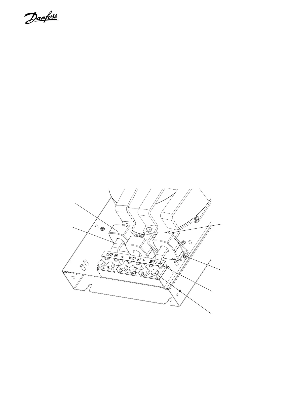
6.13 Current Sensor
1. Remove motor cabling, as required.
2. Remove input terminal mounting plate assembly
per instructions.
3. Remove terminals U, V, and W by removing 3
mounting screws. Terminal slides out from under
current sensor.
4. Disconnect current sensor cable from current
sensor.
5. Note which cables attach to which sensor for
reasembly. Remove 2 (8mm) retaining nuts from
stud on chassis baseplate and remove sensor.
Reinstall in reverse order of this procedure. Tighten 8mm
mounting nuts to 20 in-lbs (2.25 Nm).
Figure 6-12. Current Sensors
Current sensor
Terminal mounting screws (2)
Output motor cable
connection screws (2)
Terminal mounting screw
Terminal
Current sensor
mounting screws (2)

 Loading...


