EasyManuals Logo

Danfoss VLT series Service Manual

Danfoss VLT series
158 pages
To Next Page IconTo Next Page
To Previous Page IconTo Previous Page
Page #113 background imageLoading...
Page #113 background image
6-17
VLT is a registered Danfoss trademark
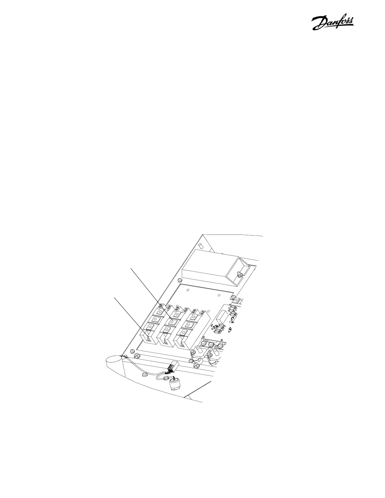
7. Note which gate leads attach to which module for
reasembly. Remove SCR/Diode gate lead
connectors from modules (not shown).
8. If unit is equipped with brake option, remove two
bus bars attaching brake IGBT module to IGBT
bus assy. Remove SCR/Diode mounting screws.
Mounting screws
(Step 8)
REASSEMBLY
1. To replace SCR/Diode modules, follow instructions
included with replacement module.
2. Reinstall module and mounting screws. Tighten
remaining T25 and 8mm screws to 20 in-lbs
(2.25 Nm) and T30 and 10 mm to 35 in-lbs (4
Nm).
3. Reassemble remaining parts in reverse order of
their removal.
Figure 6-11. D1 SCR/Diode Module (3 of 3)
SCR/Diode module

Table of Contents

Other manuals for Danfoss VLT series

Questions and Answers:

Question and Answer IconNeed help?

Do you have a question about the Danfoss VLT series and is the answer not in the manual?

Danfoss VLT series Specifications

General IconGeneral
SeriesVLT
CategoryDC Drives
Output Voltage0-100% of input voltage
Protection FeaturesOvervoltage, Undervoltage, Overcurrent, Overtemperature, Short Circuit, Ground Fault
Communication InterfacesProfibus, CANopen
Enclosure RatingIP20, IP21, IP55, IP66
Cooling MethodForced Air Cooling, Convection Cooling
Control ModeSensorless Vector, Closed Loop Vector
Ambient Temperature-10°C to +50°C (14°F to 122°F)

Related product manuals