EasyManuals Logo

Danfoss VLT series Service Manual

Danfoss VLT series
158 pages
To Next Page IconTo Next Page
To Previous Page IconTo Previous Page
Page #103 background imageLoading...
Page #103 background image
6-7
VLT is a registered Danfoss trademark
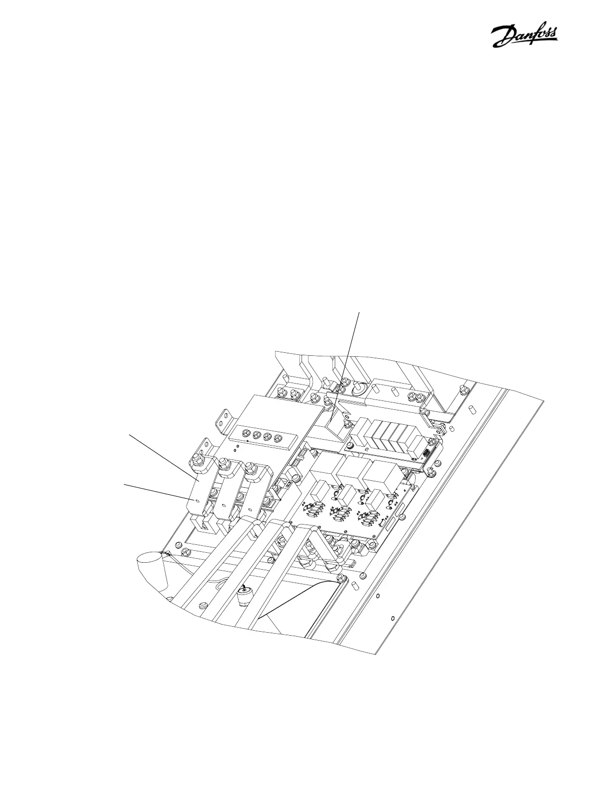
6.9 Soft Charge (SC) Resistors D1 Units
1. Remove capacitor bank per instruction.
2. Remove input terminal mounting plate per
instructions.
3. Note the color coding for each of three wires
attached to terminal 1 for each SCR/Diode
module. Ensure that correct wire is attached to
applicable stud upon reassembling. Remove
wiring from studs. Remove retaining screw (T25)
from terminal 1 of each of 3 SCR/Diode modules
and remove bus bar.
CONTINUED ON NEXT PAGE
Retaining screw
(Step 3)
Bus bar (BB2)
(Step 3)
Soft Charge Resistor
Figure 6-8. D1 Soft Charge Resistor (1 of 3)

Table of Contents

Other manuals for Danfoss VLT series

Questions and Answers:

Question and Answer IconNeed help?

Do you have a question about the Danfoss VLT series and is the answer not in the manual?

Danfoss VLT series Specifications

General IconGeneral
SeriesVLT
CategoryDC Drives
Output Voltage0-100% of input voltage
Protection FeaturesOvervoltage, Undervoltage, Overcurrent, Overtemperature, Short Circuit, Ground Fault
Communication InterfacesProfibus, CANopen
Enclosure RatingIP20, IP21, IP55, IP66
Cooling MethodForced Air Cooling, Convection Cooling
Control ModeSensorless Vector, Closed Loop Vector
Ambient Temperature-10°C to +50°C (14°F to 122°F)

Related product manuals