EasyManuals Logo

Danfoss VLT series Service Manual

Danfoss VLT series
158 pages
To Next Page IconTo Next Page
To Previous Page IconTo Previous Page
Page #108 background imageLoading...
Page #108 background image
6-12
VLT is a registered Danfoss trademark
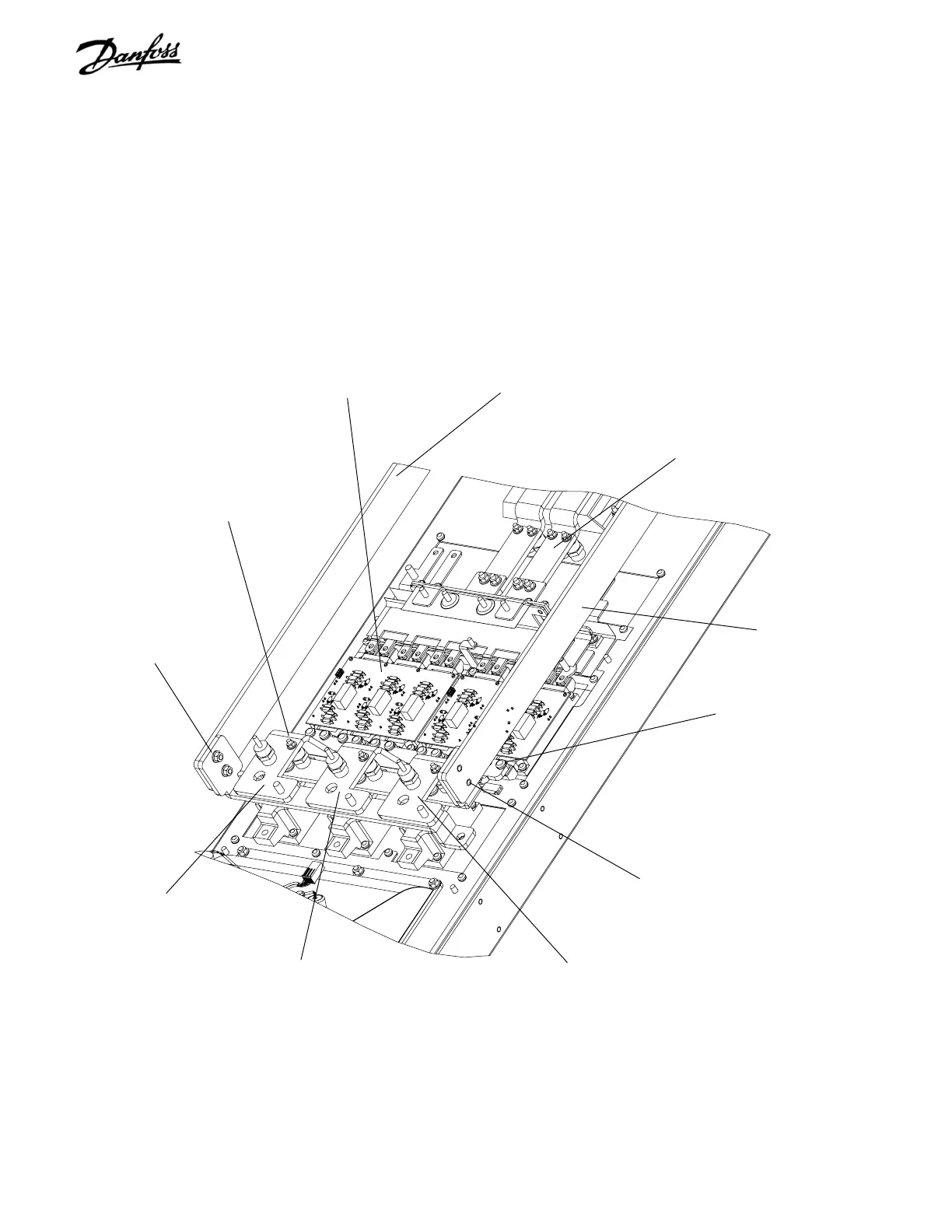
7. Remove twelve (T30) screws from output (lower)
side of IGBT modules.
8. Remove retaining nut (8mm) from each
intermediate IGBT output bus bar. Remove
intermediate IGBT bus bars.
9. Remove 4 nuts (10mm), two on either side,
connecting rectifier DC bus bars to main DC bus
bars. These are located to either side of SCR/
Diode modules.
CONTINUED NEXT PAGE
Figure 6-10. D2 SCR/Diode Module (2 of 4)
IGBT output retaining
screws (Step 7)
Retaining nut
(Step 8)
Intermediate IGBT output bus bar BB30
(Step 8)
Retaining screws
(Step 9)
Retaining screws
(Step 9)
IGBT module
Main DC bus bar BB25
(Step 9)
Bus bar BB27
Bus bar BB31
Bus bar BB30
Bus bar BB26

Table of Contents

Other manuals for Danfoss VLT series

Questions and Answers:

Question and Answer IconNeed help?

Do you have a question about the Danfoss VLT series and is the answer not in the manual?

Danfoss VLT series Specifications

General IconGeneral
SeriesVLT
CategoryDC Drives
Output Voltage0-100% of input voltage
Protection FeaturesOvervoltage, Undervoltage, Overcurrent, Overtemperature, Short Circuit, Ground Fault
Communication InterfacesProfibus, CANopen
Enclosure RatingIP20, IP21, IP55, IP66
Cooling MethodForced Air Cooling, Convection Cooling
Control ModeSensorless Vector, Closed Loop Vector
Ambient Temperature-10°C to +50°C (14°F to 122°F)

Related product manuals