EasyManuals Logo

Danfoss VLT series Service Manual

Danfoss VLT series
158 pages
To Next Page IconTo Next Page
To Previous Page IconTo Previous Page
Page #120 background imageLoading...
Page #120 background image
6-24
VLT is a registered Danfoss trademark
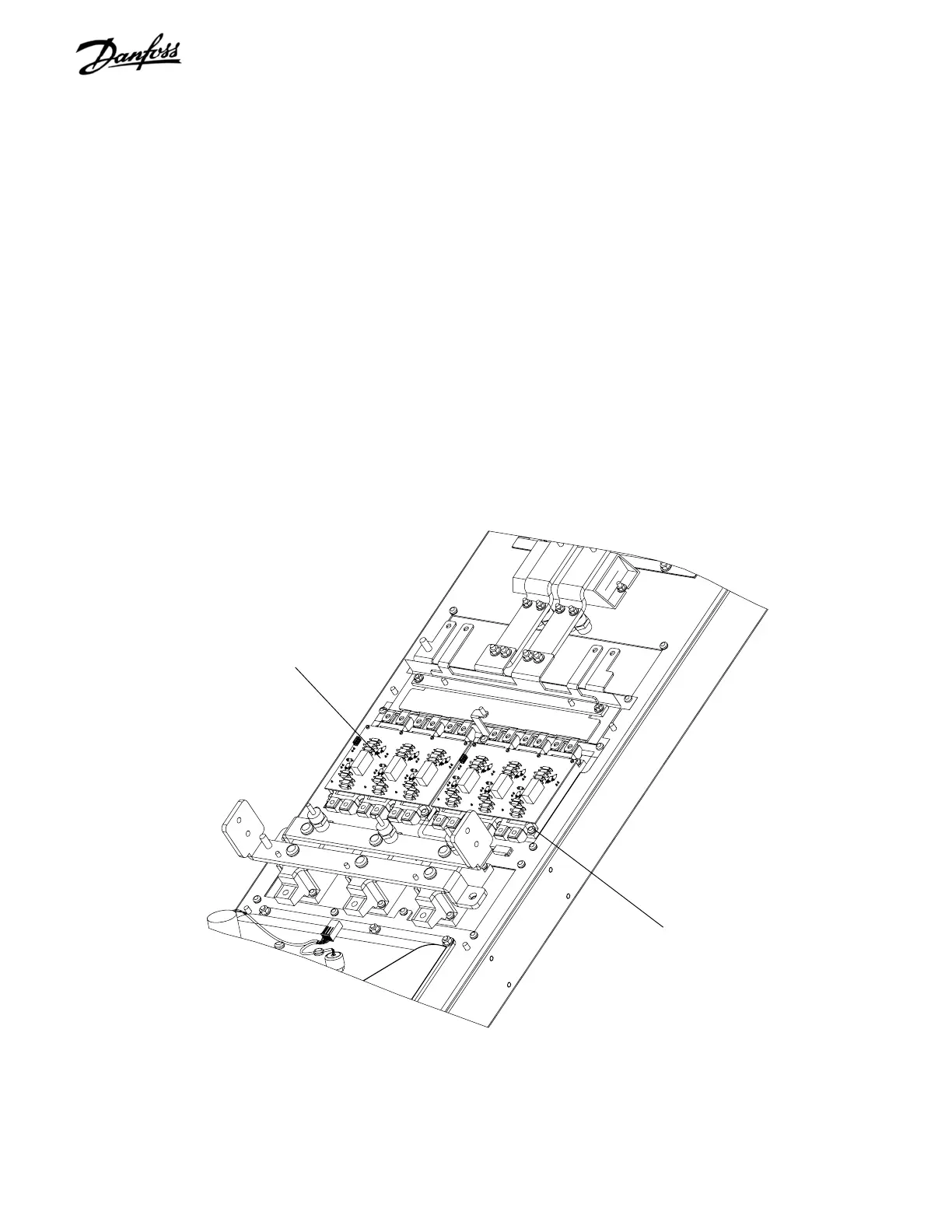
Figure 6-15. D2 IGBT Modules (3 of 3)
IGBT module
Retaining screw
(Step 13)
13. Remove 2 IGBT modules by removing 16
retaining screws (8 per module) and slide modules
free from under bus bars.
14. Clean heatsink surface with mild solvent or alcohol
solution.
REASSEMBLY
1. Replace IGBT module in accordance with
instructions provided with replacement unit.
2. Reassemble remaining parts in reverse order of
their removal.
3. Reinstall module and mounting screws. Tighten
remaining T25 and 8mm screws to 20 in-lbs (2.25
Nm) and T30 and 10 mm to 35 in-lbs (4 Nm).

Table of Contents

Other manuals for Danfoss VLT series

Questions and Answers:

Question and Answer IconNeed help?

Do you have a question about the Danfoss VLT series and is the answer not in the manual?

Danfoss VLT series Specifications

General IconGeneral
SeriesVLT
CategoryDC Drives
Output Voltage0-100% of input voltage
Protection FeaturesOvervoltage, Undervoltage, Overcurrent, Overtemperature, Short Circuit, Ground Fault
Communication InterfacesProfibus, CANopen
Enclosure RatingIP20, IP21, IP55, IP66
Cooling MethodForced Air Cooling, Convection Cooling
Control ModeSensorless Vector, Closed Loop Vector
Ambient Temperature-10°C to +50°C (14°F to 122°F)

Related product manuals